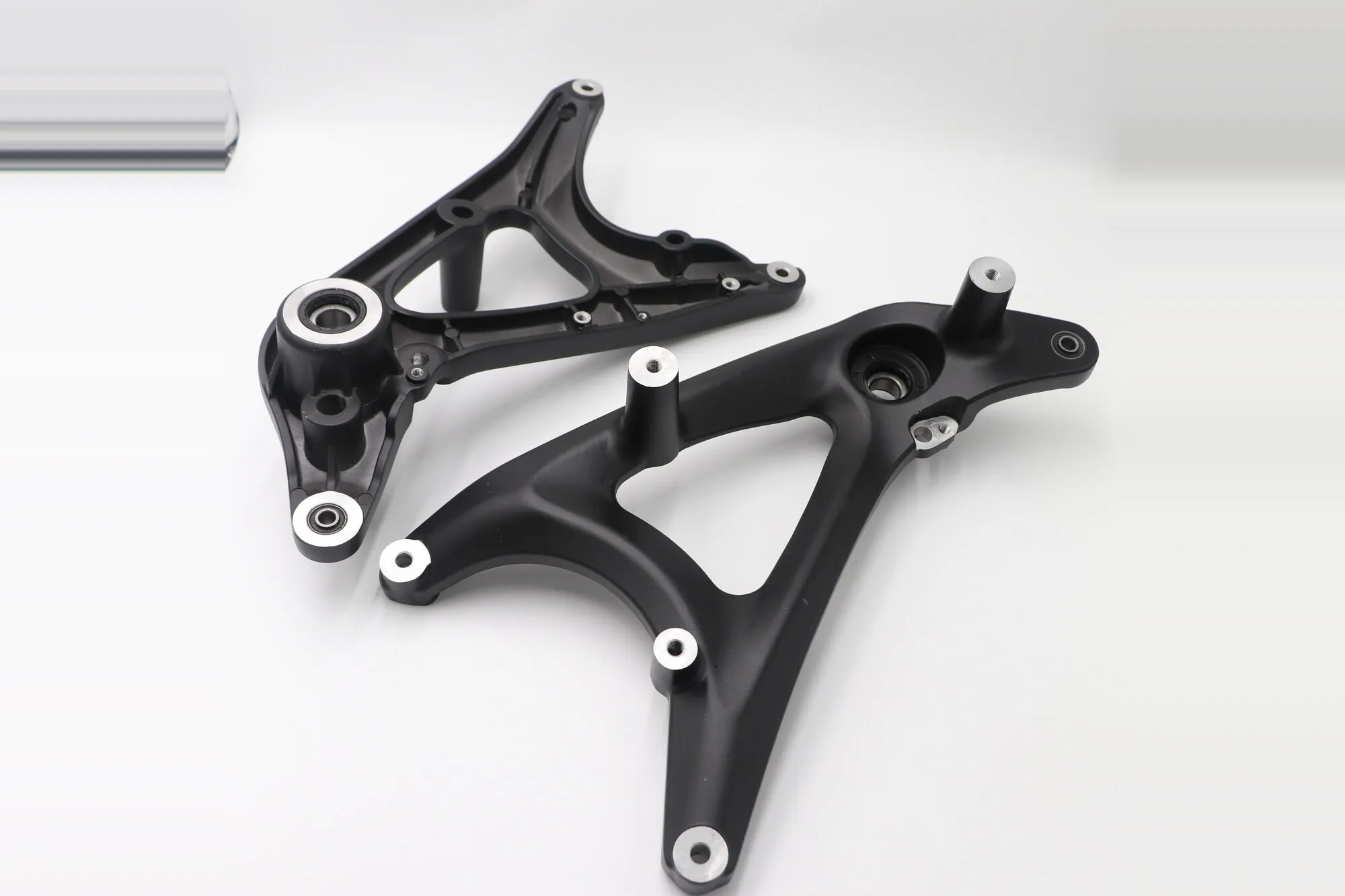
Linkage arms
Matched pair — the reason five-axis matters is that the bore axes must agree between them.
Three-, four- and five-axis milled parts — from small clamp blocks in repeat quantities to large structural housings and long frame rails where flatness across the whole part is the specification.
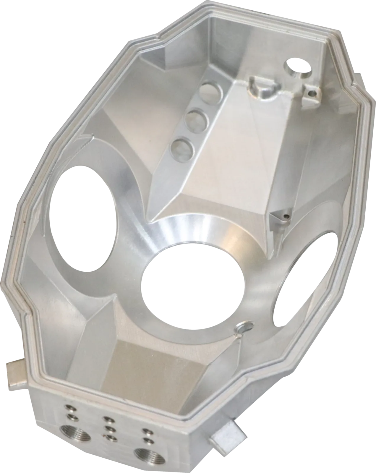
Almost none of the difficulty in these parts is in removing the metal. It is in the part staying where you put it. A long frame rail relieves internal stress as it is cut and bows; a thin-wall plate flexes away from the cutter and springs back afterwards; a five-axis housing needs its bores concentric across faces that are never presented to the spindle in the same orientation.
So the work is in fixturing, cut sequence and stress relief between roughing and finishing — decisions that are invisible in the finished part and are most of what separates one made right from one made once. Where a drawing asks for something that will fight the process, we say so at DFM review rather than after the first article.
Compound-angle and organic geometry, where the datum has to hold across faces the spindle sees from different directions.
Matched pair — the reason five-axis matters is that the bore axes must agree between them.
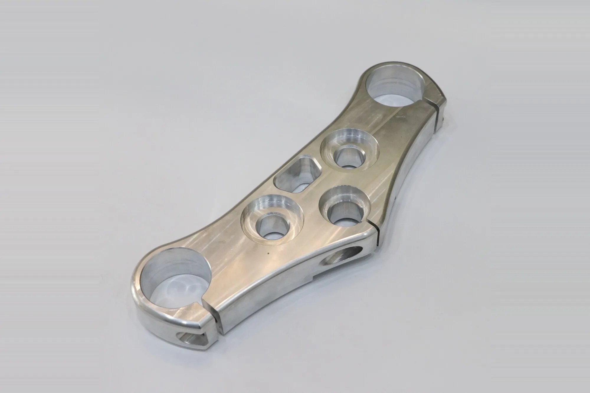
Clamped tube seats bored parallel, then the outside polished.
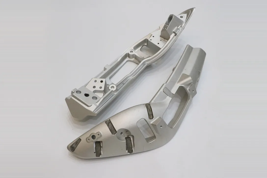
Compound-angle faces and pockets on both sides.
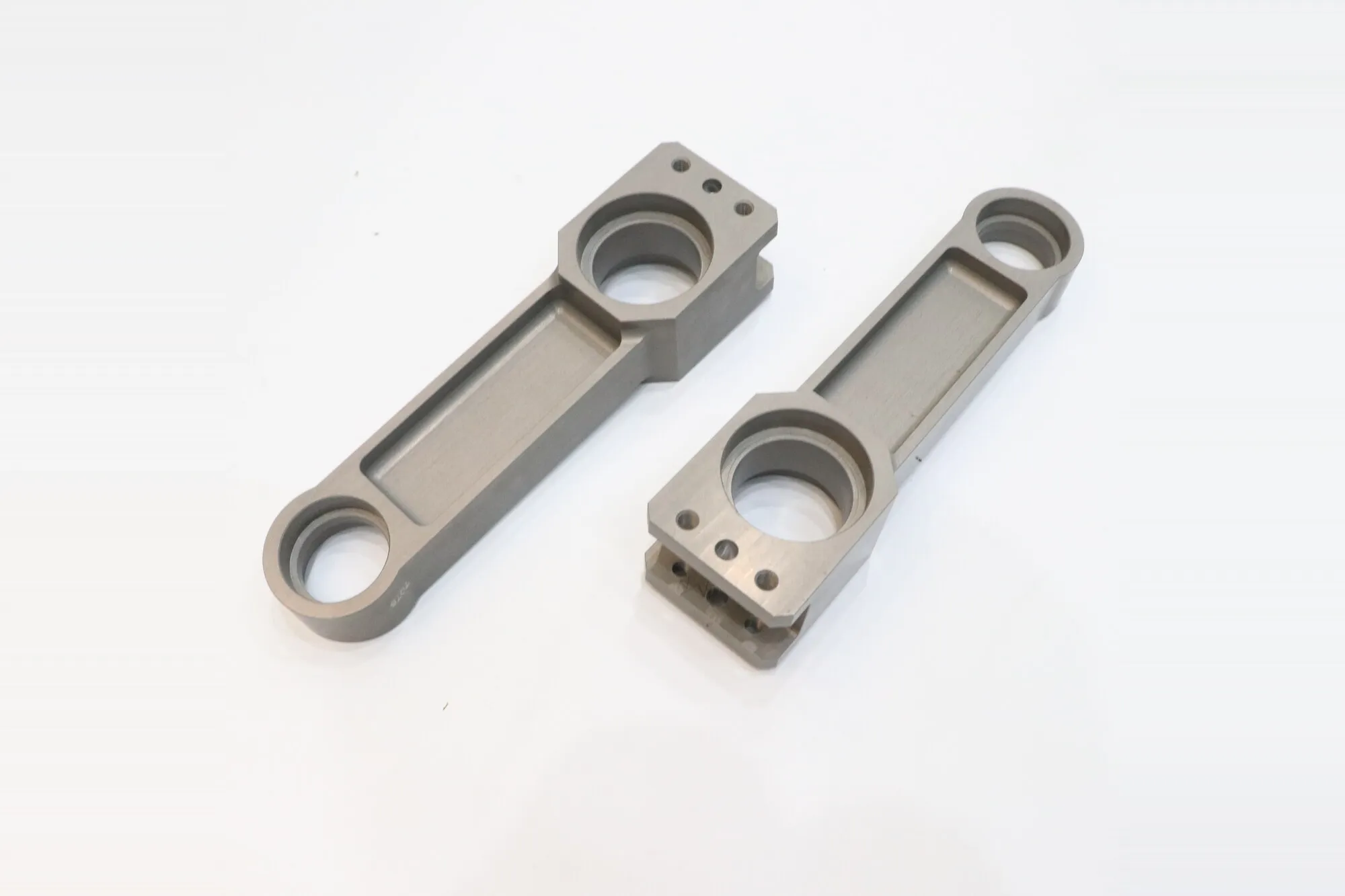
Bore-to-bore centre distance is the dimension that matters here.
Long and large components where the tolerance is not on any single feature but on flatness and hole position across the whole envelope.
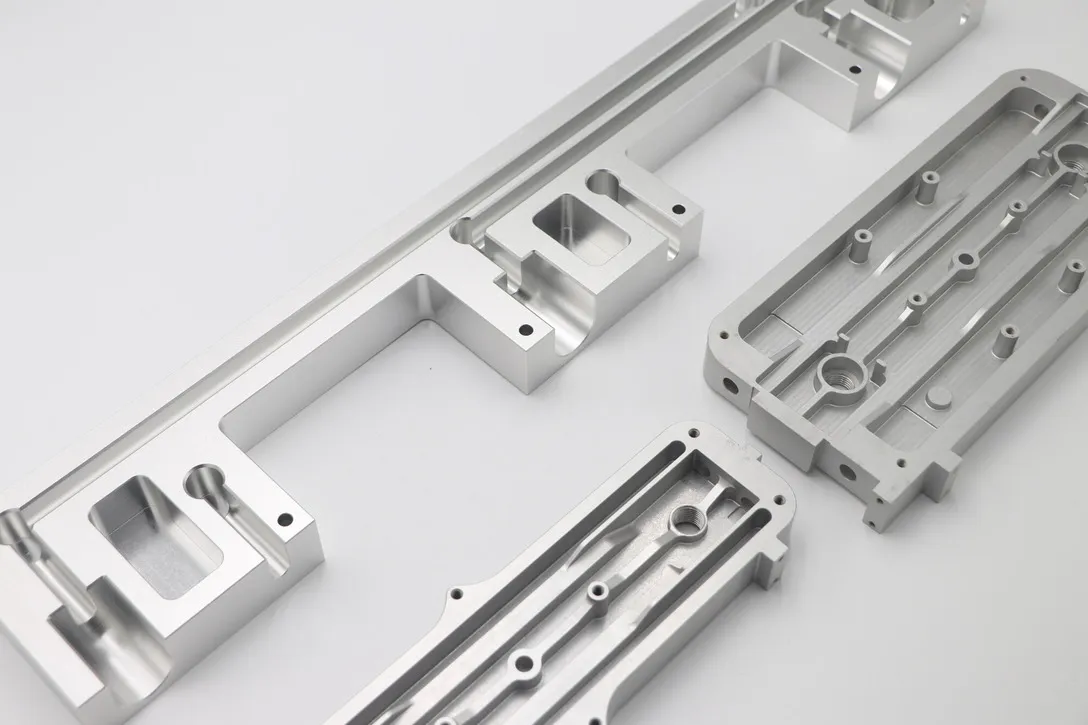
Stress-relieved between roughing and finishing so they stay straight.
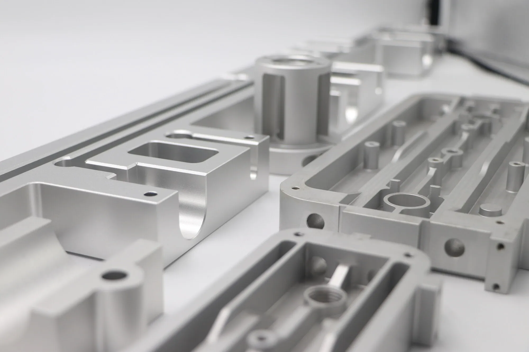
Pocket floors and bored seats on a single reference.
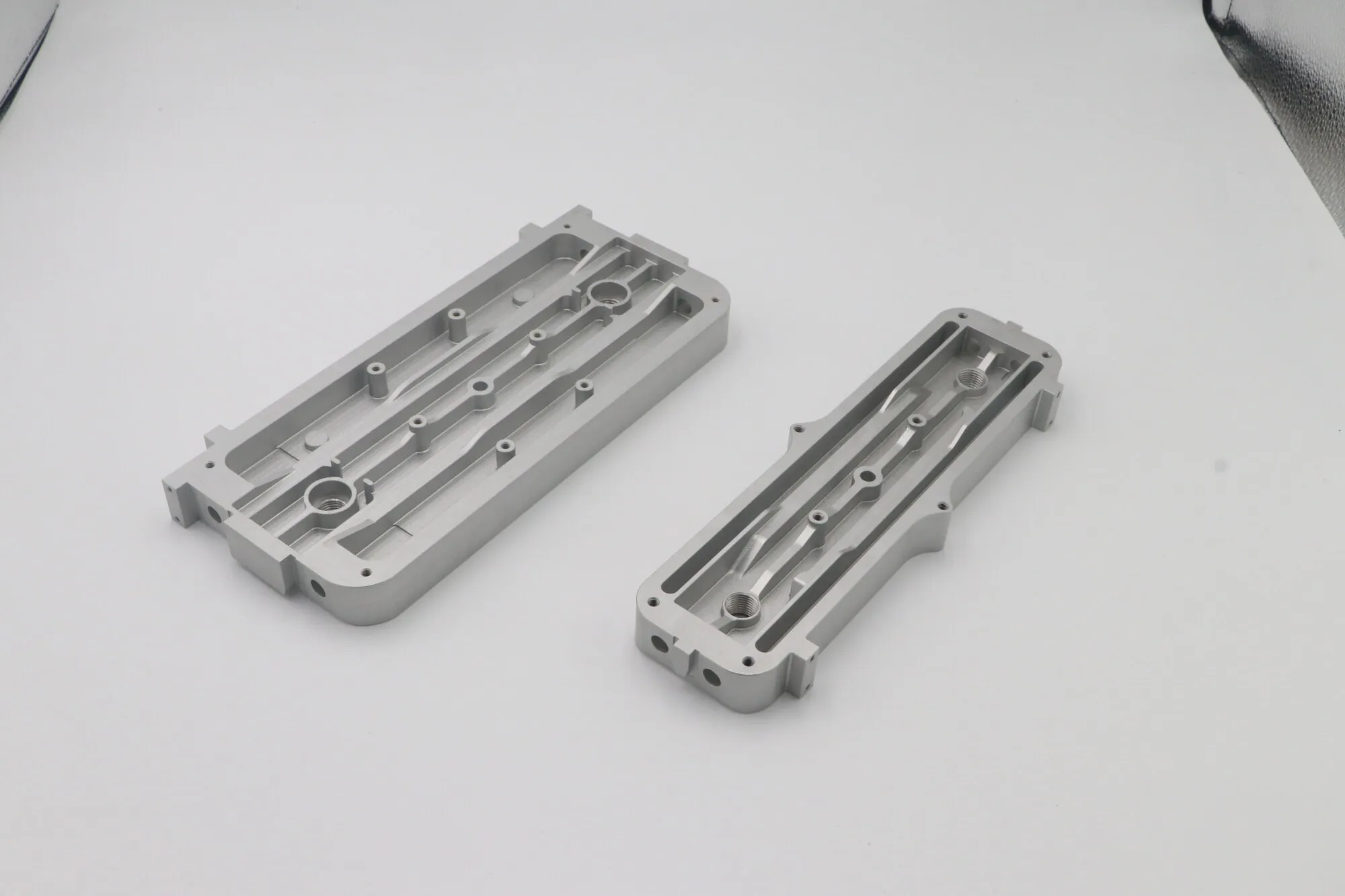
Internal channels and a seal groove that has to stay flat under bolt load.
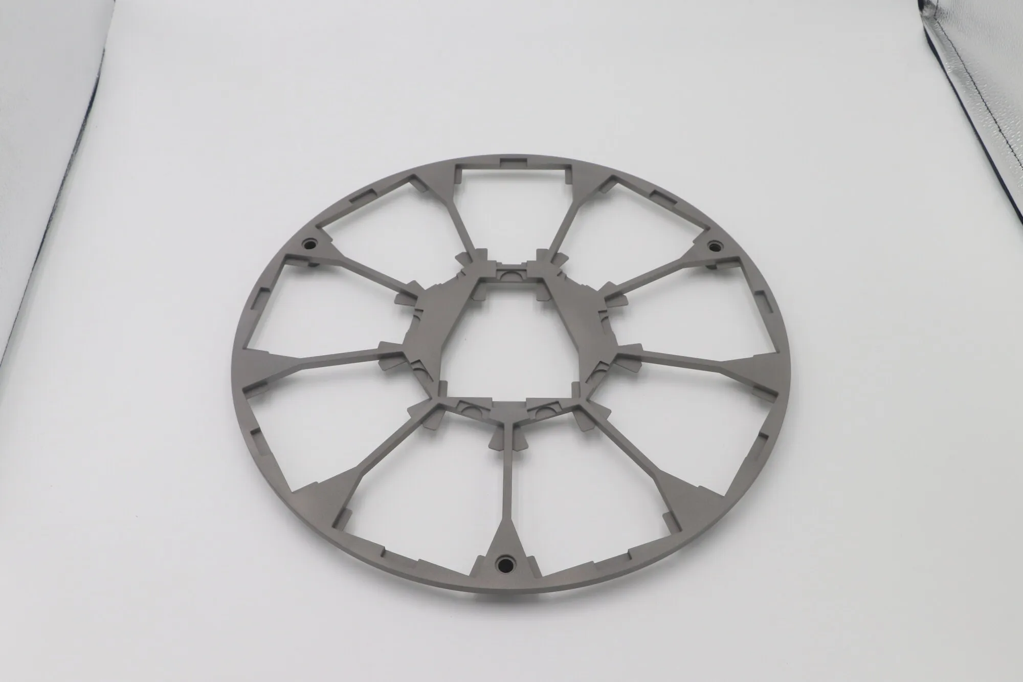
Large diameter, thin radial webs — supported through the cut so it doesn't chatter.
Plates taken down to the minimum section that still carries load. The limit is not the cutter, but how much the part deflects during cutting and relaxes or distorts after unclamping.
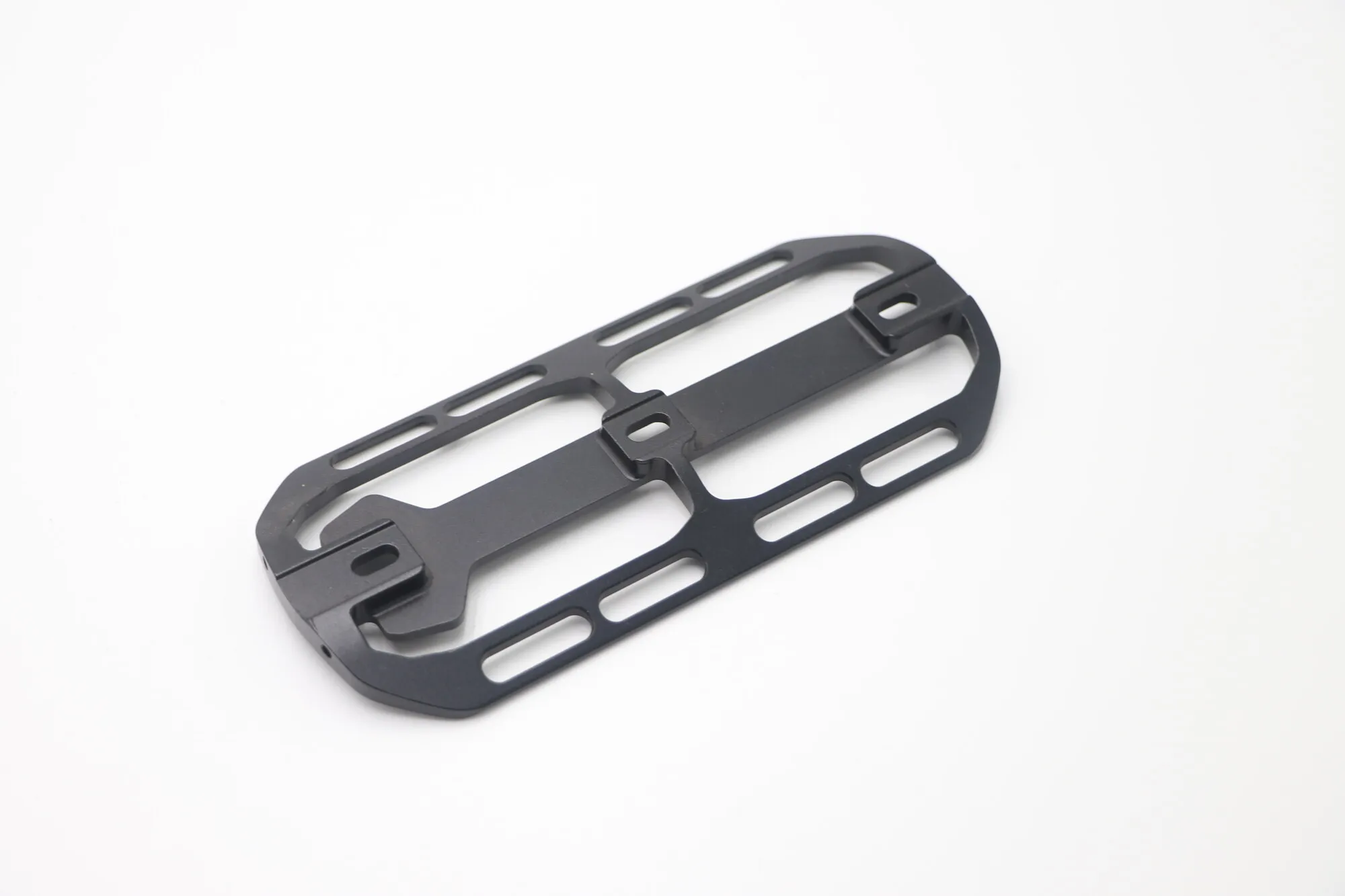
Long slots and thin webs, anodized black after machining.
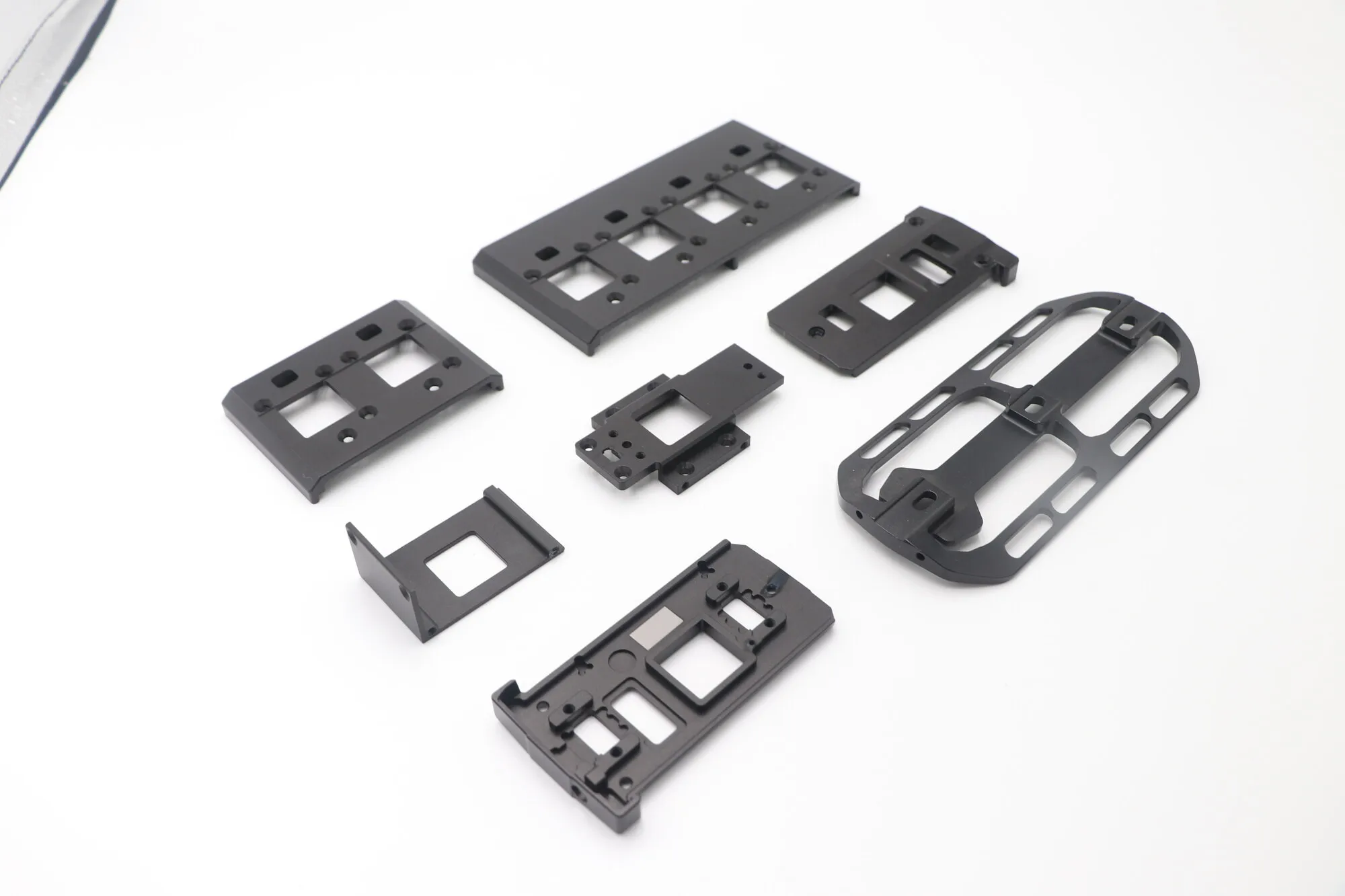
A family of plates lightened to different degrees from the same stock.
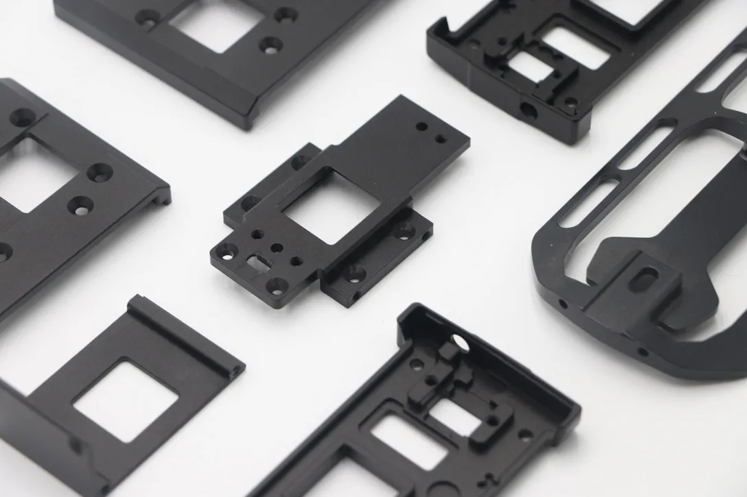
Production group, where flatness has to repeat part to part.
Smaller milled parts in repeat quantities. The engineering question shifts from 'can it be made' to 'does part 500 measure the same as part 1'.
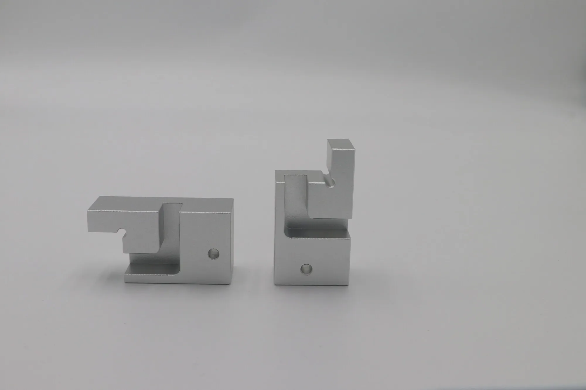
Slotted and stepped brackets machined as a matched pair.
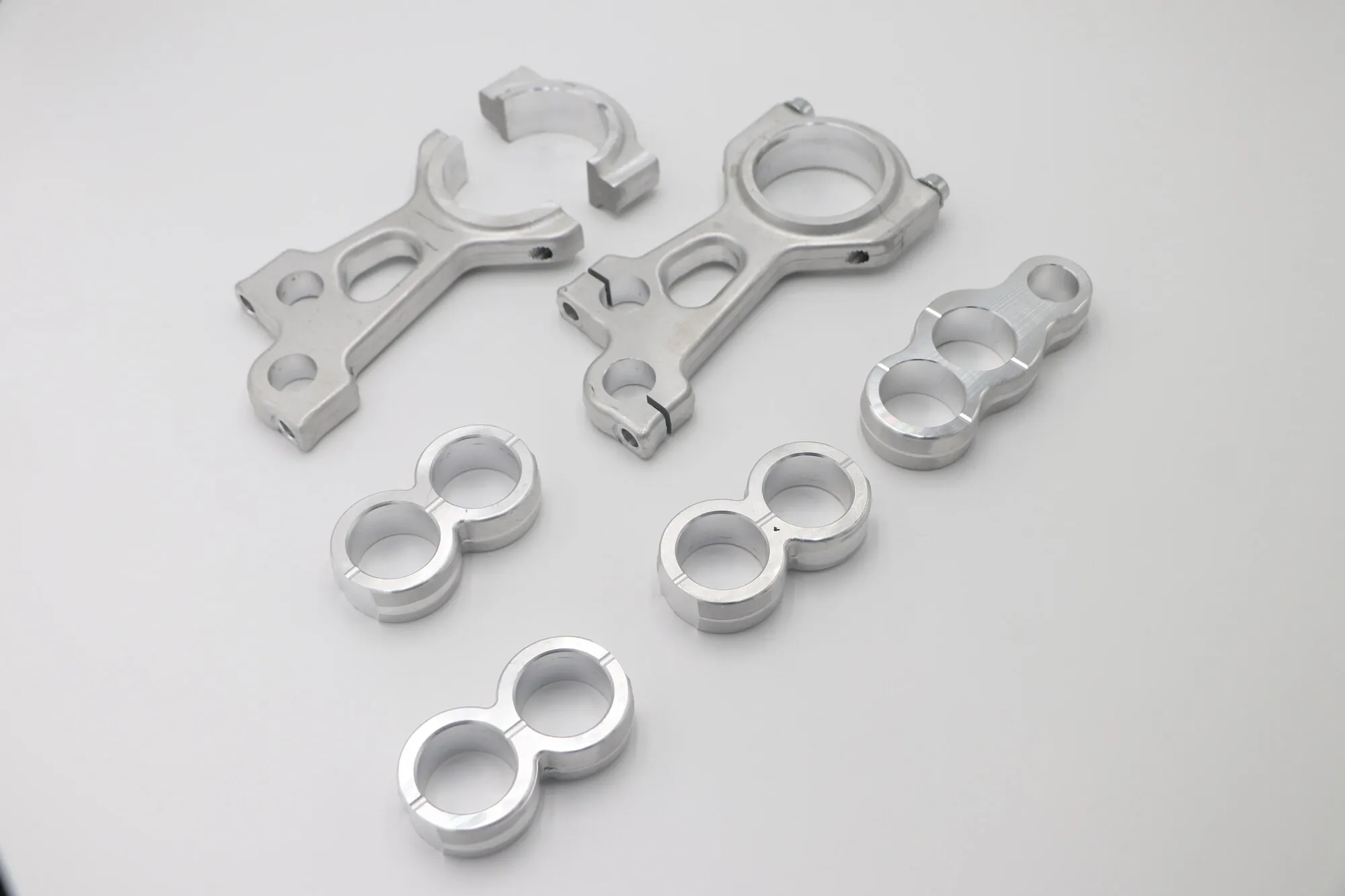
Forked brackets where both bores must share an axis.
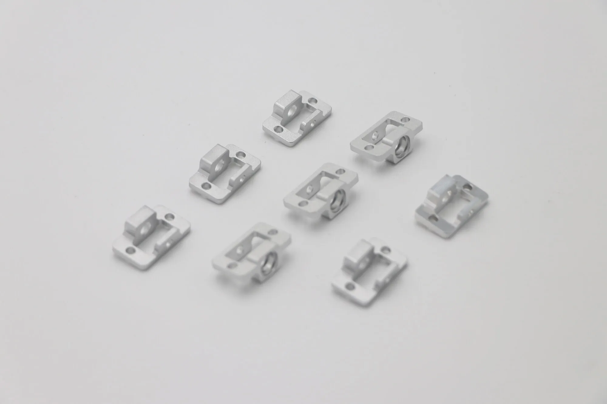
Eight identical parts — the point of the photo is that they are identical.
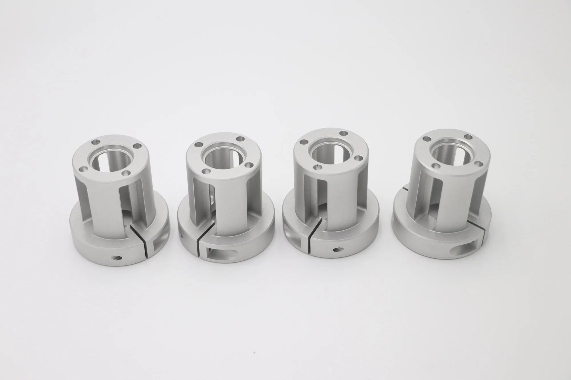
Slit after boring, so the bore is round before it is relieved.
Not every part should be aluminum. PEEK where the part must be electrically or thermally isolating and dimensionally stable, POM where it has to slide, steel where it has to take load or wear.
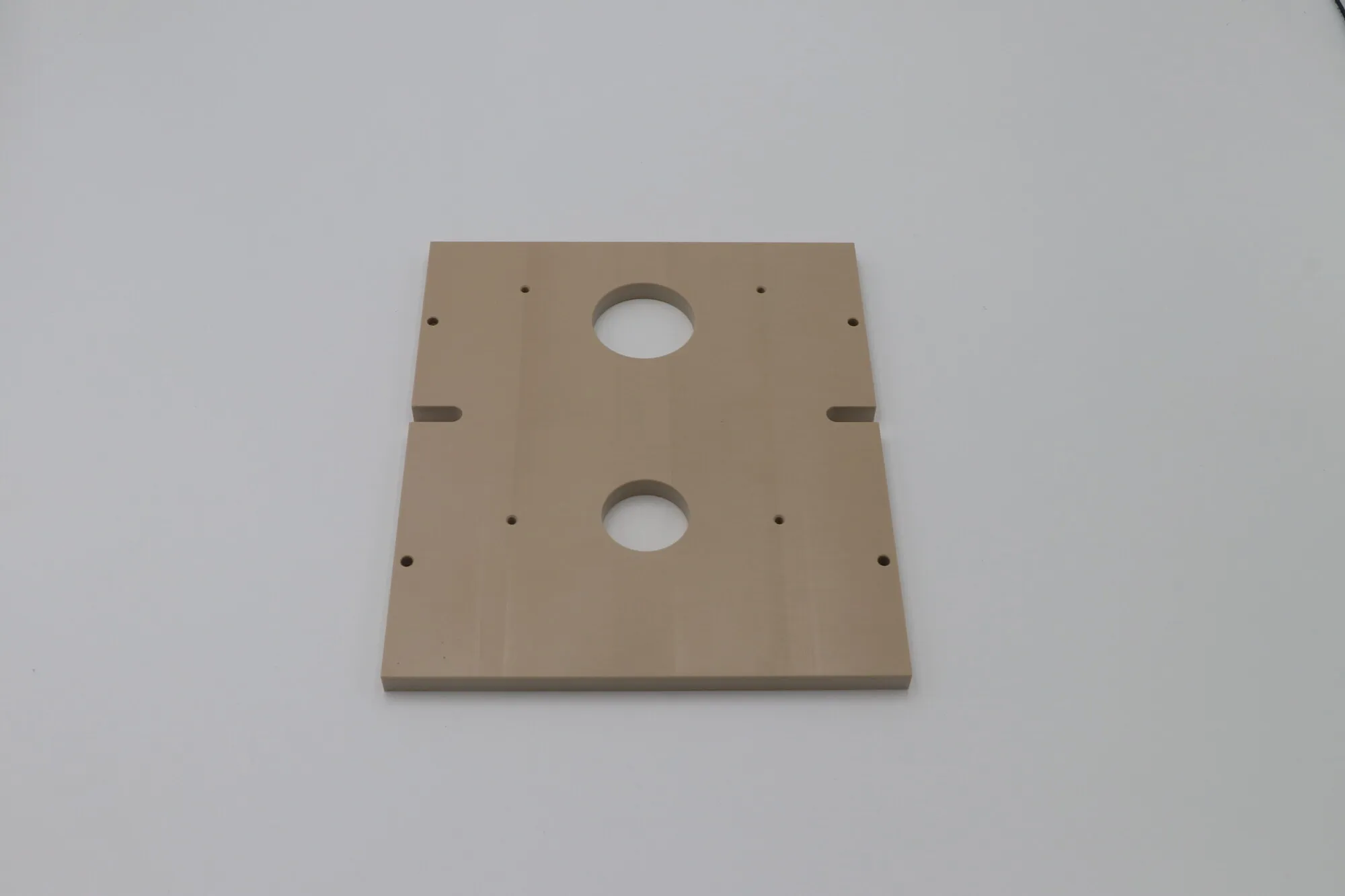
Machined PEEK — low cutting forces, but it moves with temperature and moisture.
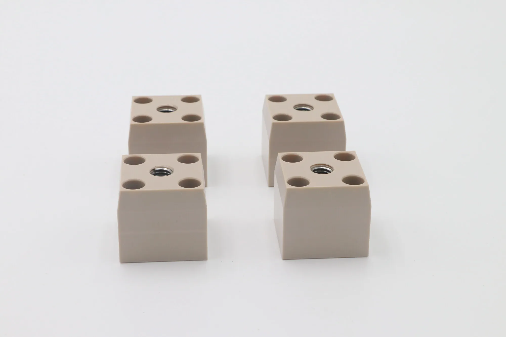
Tapped and counterbored PEEK for insulating mounts.
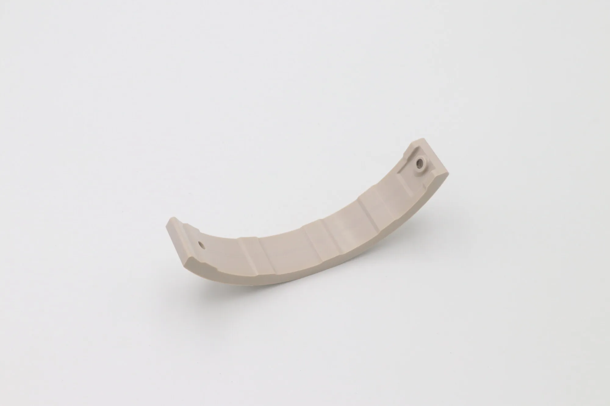
Curved profile machined from solid rather than formed.
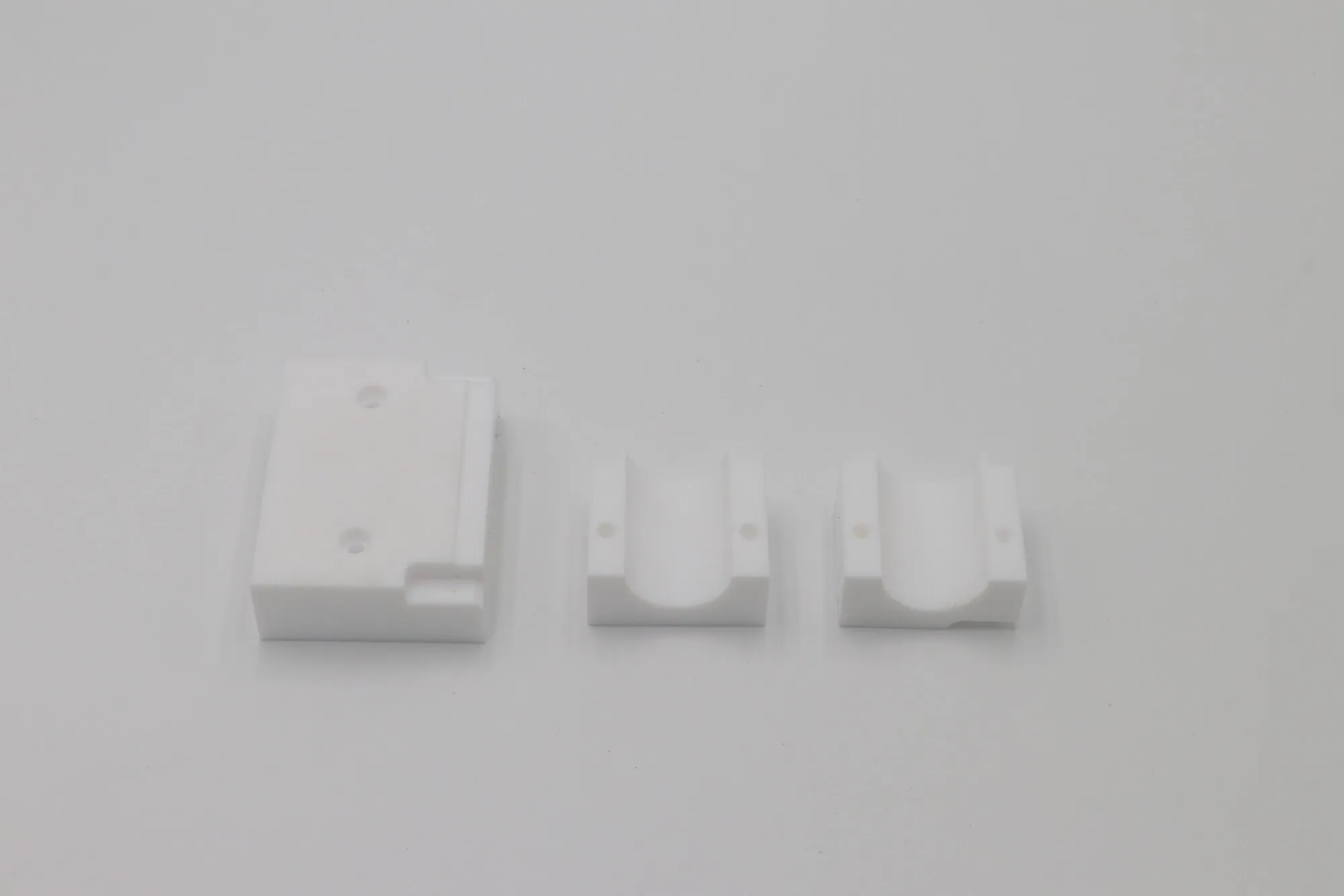
Acetal carriers where the part has to slide, not grip.
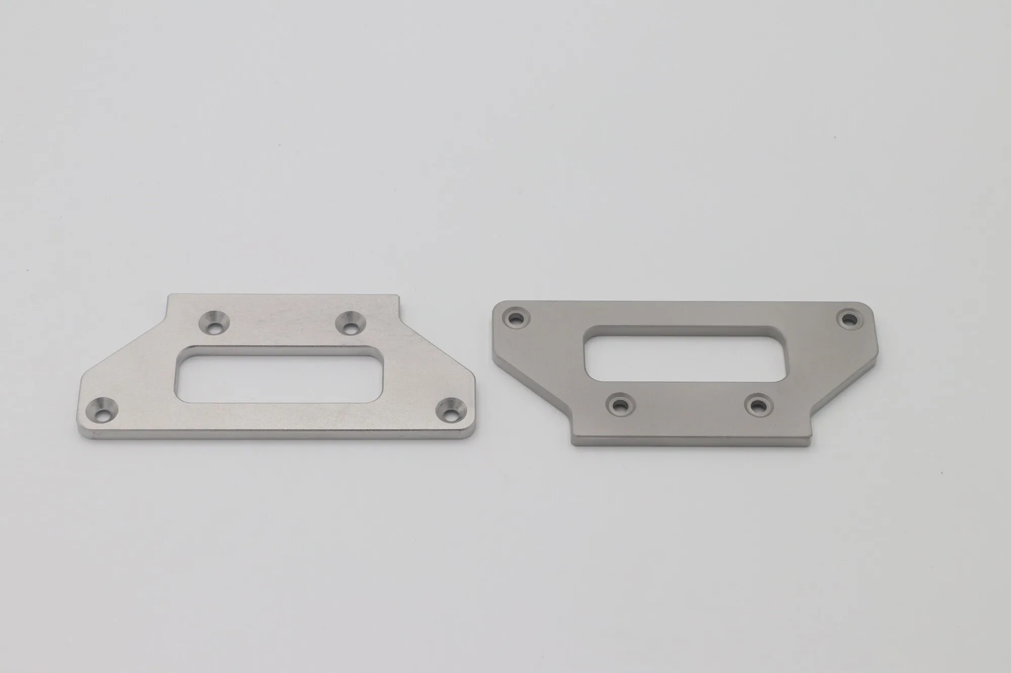
Milled steel plate with apertures and countersinks.
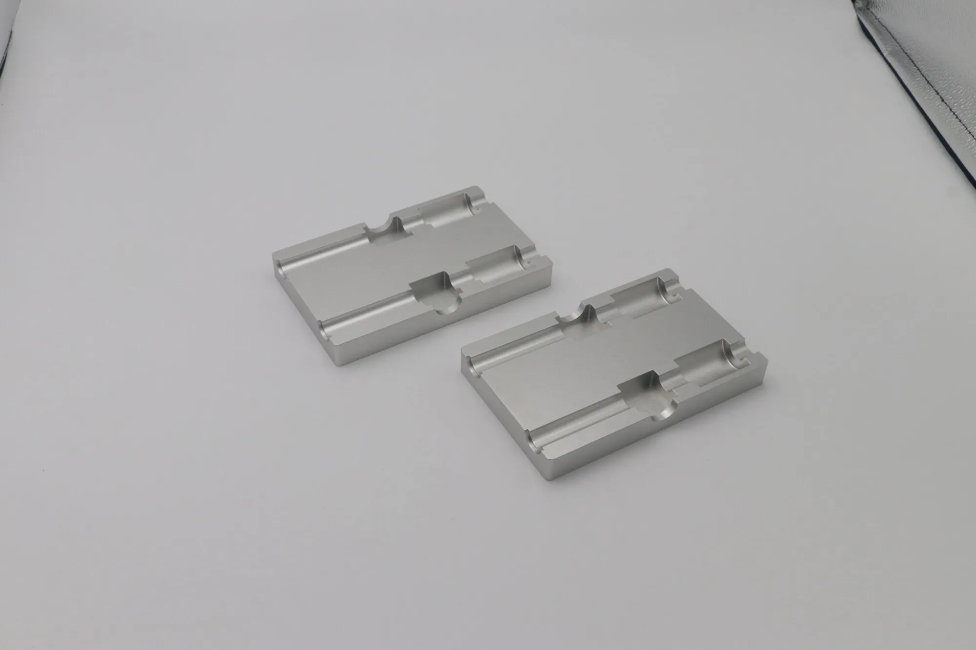
Stepped and bored, in matched sets.
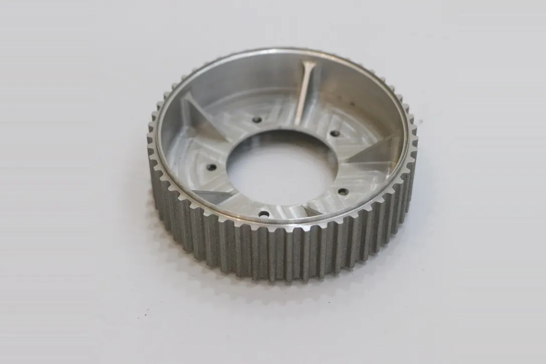
Cut tooth form with a bored and keyed hub.
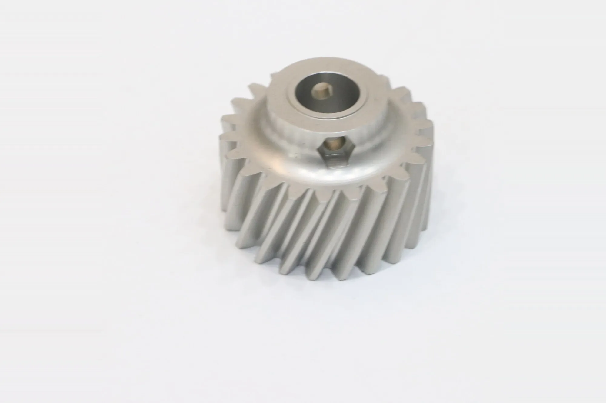
Cut gear teeth on a machined blank.
Routine figures for the part families above, not the tightest achievable. Which feature actually controls the assembly matters more than the tightest number on the drawing.
±0.02 mm on machined features as a normal expectation, tightening per feature where a fit depends on it.
Held across the whole envelope rather than locally, which on long rails means stress relief between roughing and finishing — not a final skim.
Bores and faces that must agree across orientations are cut without re-fixturing, so their relationship comes from the machine rather than from a setup.
Down to around 0.8 mm in aluminum depending on span and geometry. Below that the achievable tolerance is set by springback, so we quote it per part.
Wall thickness, span and material all interact — a 1 mm wall over 20 mm behaves nothing like 1 mm over 200 mm. Send the geometry and we will tell you what will hold its shape rather than quoting a single number.
In aluminum, down to roughly 0.8 mm depending on how far it spans and what supports it. The honest answer is that wall thickness on its own does not determine feasibility: a 1 mm wall 20 mm across is straightforward, the same wall over 200 mm will deflect under the cutter and spring back afterwards. Send the geometry and we will tell you what will hold its shape, and where adding a rib would cost less than tightening a tolerance.
Yes. It matters when features on different faces have to agree with each other — bore axes that must be parallel, or a compound angle referenced to a datum on another face. Cutting those in one orientation removes the setup error entirely. For a part that is essentially prismatic, three-axis work in two setups is often cheaper and just as accurate, and we will say so rather than quoting the more expensive route.
By cutting them in stages. Stock carries internal stress, and removing material unevenly lets it move — so a long rail roughed to shape and then finished in the same setup will come off straight and bow later. We rough, allow the part to relieve, then finish, and fixture so clamping is not itself inducing the distortion. This is why a long frame rail costs more per hour of cutting than its shape suggests.
Yes — PEEK, POM and similar. They cut easily but hold tolerance differently from metal: PEEK moves noticeably with temperature and, over time, with moisture, so a dimension measured warm off the machine is not the dimension you will receive. We let parts stabilise before final inspection. If your tolerance is tight enough for that to matter, tell us the service temperature and we will discuss whether the material can actually hold it.
We machine cut tooth forms — timing pulleys and pinions like those shown above — on machined blanks. For high-volume or high-precision gearing to a specific AGMA or DIN quality class, tell us the class you need up front, because that is a different process question from simply cutting a tooth profile and we would rather establish it before quoting.
The parts on this page run from clamp blocks a few centimetres across to structural housings and frame rails several hundred millimetres long. Rather than publish an envelope that may not match your part's real constraint, send the overall dimensions and we will confirm — for large parts the limiting factor is often the fixturing and the reach needed for a specific feature, not the table size.
Send your STEP file and drawing with the material, quantity, critical tolerances and which datum features control the assembly. We will review it for manufacturability and come back with a quotation.
Get a Quote