CNC Machining Tolerance Guide

CNC machining tolerances define the acceptable variation allowed between a part’s nominal drawing dimension and the finished component. Clear tolerance planning helps align functional requirements, machining approach, inspection expectations, finishing needs, and project cost.

This CNC tolerance guide explains the practical information that engineers and buyers should provide when requesting custom CNC machined components, including critical dimensions, datums, threads, surface requirements, and assembly interfaces.

Upload Drawings & Get a Quote →
CNC milling cutter machining a metal part on a vertical machining centre.

What CNC Machining Tolerance Means

A nominal dimension is the target size shown on a drawing, such as a hole diameter, part length, or shaft diameter. A tolerance range defines how much the completed feature may vary from that target while remaining acceptable for its intended function.

A critical feature is a dimension, location, geometric relationship, or surface condition that directly affects fit, movement, sealing, alignment, assembly, or another functional requirement. These features should be clearly identified on the drawing rather than left to general assumptions.

Vernier calipers resting on a printed engineering drawing.

CNC machining tolerances are not determined by one factor alone. They can depend on part geometry, material behavior, machining process, feature accessibility, finishing sequence, quantity, and inspection method. A drawing review before quotation helps clarify which requirements need closer feasibility evaluation.

Factors That Affect Achievable Tolerances

Part Geometry and Feature Access

Complex geometry, restricted tool access, internal corners, deep pockets, intersecting features, and multiple setup requirements may influence dimensional control. Tolerance feasibility can depend on whether a feature can be reached, supported, and measured consistently. Features with limited access should be reviewed during RFQ evaluation.
Material Behavior

Different materials may respond differently to cutting forces, heat, internal stress, and clamping pressure. Softer materials may be more sensitive to deformation, while harder or heat-resistant materials may require different machining strategies. Material grade and material condition should be reviewed alongside tolerance requirements.

Part Size and Wall Thickness

Large parts, thin walls, long unsupported sections, and flexible geometries may be more sensitive to movement during machining or inspection. Dimensional variation can depend on how the part is held, machined, and released from fixturing. Wall thickness and overall part proportions should be reviewed with critical dimensions in mind.
CNC Milling vs. CNC Turning

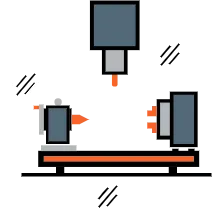
CNC milling and CNC turning control different feature types through different cutting and workholding approaches. A tolerance that is practical for a turned diameter may require a different review when applied to a milled feature. The selected process should be considered together with part geometry and drawing requirements.

Surface Finishing and Secondary Processes

Anodizing, plating, coating, polishing, blasting, heat treatment, and other secondary processes may affect surface condition, build-up, edge definition, or final dimensions. When a finished dimension is critical, the drawing should clarify whether it applies before or after finishing. Finishing sequence should be reviewed before quotation.

Datum Strategy and Inspection Method

Tolerance evaluation depends on how features are referenced and measured. Clear datums help establish the intended relationship between holes, faces, shafts, and other functional features. Inspection requirements can depend on datum selection, measurement access, part stability, and the documentation expected for the project.


CNC Tolerance Considerations by Feature Type

Feature TypeWhat to Define on the DrawingCommon Manufacturing Considerations
Linear DimensionsNominal size, applicable tolerance, and reference surfacesLong dimensions, multiple setups, material movement, and inspection access may affect planning.
Hole DiametersDiameter, tolerance, depth, location relative to datums, and whether through or blindTool access, hole depth, intersection with other features, and finishing requirements should be considered.
Shaft DiametersNominal diameter, tolerance, length, and mating functionConcentricity, runout expectations, workholding, and mating-part fit may require review.
Threads and Tapped HolesThread designation, pitch, class if required, depth, and quantityThread depth, blind-hole clearance, material, access, and post-finishing requirements should be confirmed.
Flatness and PerpendicularityControlled surfaces, datum references, and geometric tolerance requirementsPart rigidity, fixturing, machining sequence, and measurement method may influence feasibility.
Deep Pockets and Thin WallsFeature depth, wall thickness, tolerance, and critical surfacesTool reach, chatter risk, deflection, heat, and part support should be reviewed.
Edge Breaks and DeburringChamfer, radius, edge-break note, or deburring requirement“Remove sharp edges” may need clarification when edge geometry or assembly fit is important.
Surface Finish RequirementsRequired surface roughness or finishing condition, applicable surfaces, and whether requirements apply before or after finishingTool marks, polishing, coating, blasting, or plating may affect appearance and final dimensions.

Milling and Turning: Planning Considerations

CNC Milling

CNC milling is commonly used for prismatic parts and features such as pockets, slots, profiles, faces, drilled holes, threaded holes, and contoured features requiring multiple tool orientations. Drawings should identify critical dimensions, datum references, hole locations, pocket depths, internal corner radii, surface requirements, and surfaces with specified appearance or functional finish requirements.

Before quotation, manufacturability should be reviewed for tool access, internal corner conditions, deep cavities, thin walls, feature orientation, number of setups, and the relationship between critical features. If geometry includes complex surfaces or multiple features controlled from a common datum scheme, an engineering review can help clarify the intended inspection approach.

CNC milling operation with coolant flooding the cutting tool.

CNC Turning

CNC turning is commonly used for rotational features such as shafts, bushings, pins, sleeves, collars, threaded sections, bores, grooves, and stepped diameters. Drawings should clearly define diameters, lengths, threads, chamfers, radii, groove details, concentricity expectations, and the functional relationship between mating diameters.

Before quotation, feasibility should be reviewed during RFQ evaluation for workholding, part length-to-diameter relationship, thin-walled sections, internal bores, deep drilled features, interrupted cuts, post-machining finishing, and measurement access. Where a turned component includes milled flats, cross-holes, or keyways, the relationship between turning and secondary operations should also be reviewed.

CNC turning operation machining a rotational metal component.

How to Specify Tolerances on a Drawing

  1. Identify Critical Functional Dimensions

    Mark dimensions that affect fit, sealing, alignment, movement, load transfer, or assembly. Avoid applying the same tight tolerance to non-critical features without a functional reason.

  2. Reference Clear Datums

    Establish datum surfaces or axes that reflect how the part functions in an assembly. Clear datums support more consistent communication of feature location and geometric requirements.

  3. Define Thread Specifications Completely

    Include thread size, pitch, depth, through or blind condition, thread tolerance class where required, and any finishing or masking needs that may affect threaded features.

  4. Clarify Surface Finish Requirements

    State which surfaces require a specific finish, texture, coating, plating, or appearance condition. Clarify whether final dimensional requirements apply before or after secondary processing.

  5. Share Mating-Part or Assembly Information When Relevant

    A mating-part drawing, assembly view, fit requirement, or functional explanation can help identify which dimensions require closer control and which can remain less restrictive.

When Engineering Review Is Recommended

An engineering feasibility review is recommended before quotation when a part includes:

  • Tight or non-standard tolerances
  • Multiple critical features controlled from a common datum scheme
  • Thin walls, long unsupported sections, or deep cavities
  • Surface finishing or secondary processes after machining
  • Mating components, press fits, sealing interfaces, or assembly relationships

Early review does not replace the customer’s design authority. It helps clarify manufacturing considerations and identify questions that may need resolution before production planning.

Engineer measuring a machined component during inspection review.

Related Resources

Need to Discuss Drawing Requirements?

Tolerance requirements are most useful when they are connected to part function, assembly conditions, material choice, and finishing sequence. Share your drawing, 3D model, quantity, material preference, and any critical dimensions so the project requirements can be reviewed before quotation.

Upload Drawings & Get a Quote →