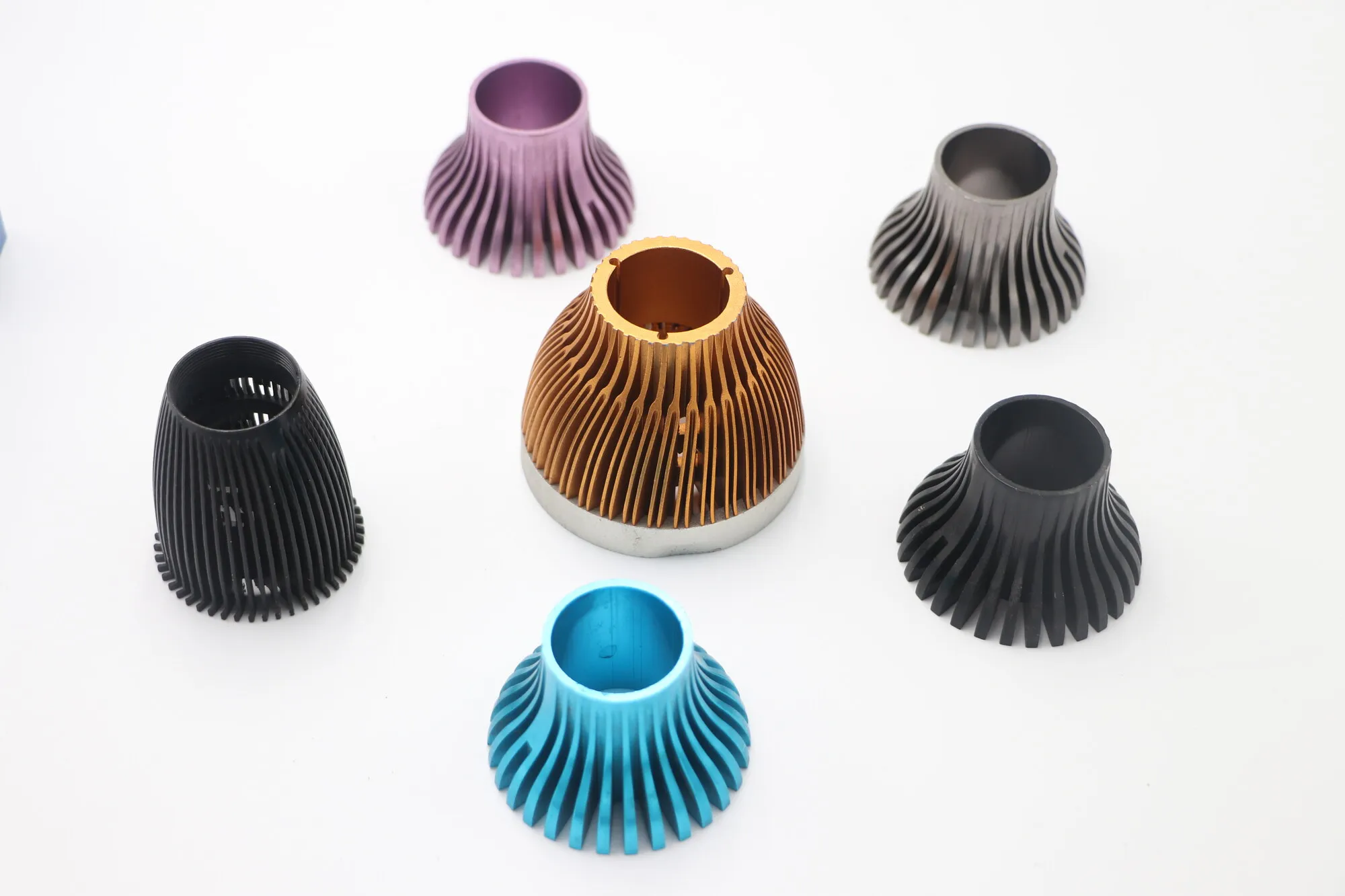
Color anodized LED lamp heat sinks
Radial fins on a turned conical body, finished across a full anodize color range — color supports product appearance, while darker finishes can also increase surface emissivity.
Heat sinks and cooling components in 6061 and 6063 aluminum — radial-fin lamp bodies turned and milled from solid, and extruded fin profiles machined to length.
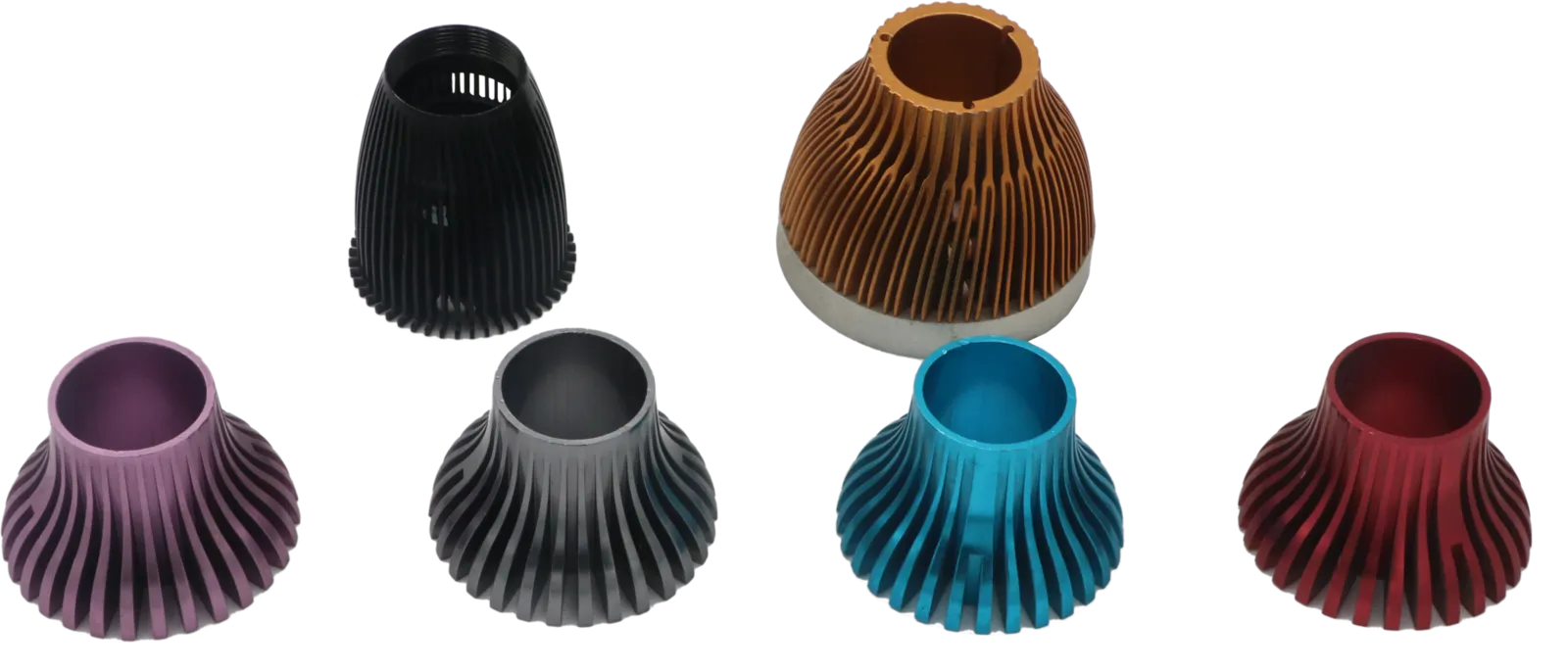
Thermal performance wants fins that are thin, tall and closely spaced — which is exactly the geometry that chatters under a cutter, bends when handled, and traps anodizing solution between fins so the color comes out uneven. Every gain in surface area costs something in machinability.
The other decision worth making early is extrusion versus solid. A fin profile pushed through a die is dramatically cheaper per part than one milled from billet, but carries tooling cost and constrains the cross-section to something constant along its length. Below a few hundred parts, machining from solid usually wins; above it, rarely. We will cost both rather than assume.
Finish matters thermally, not just visually: black anodize raises emissivity, which is why so many heat sinks are black. On a part cooled mostly by airflow the color is close to irrelevant, so if yours is visible in the product you can choose freely.
Turned bodies with radial fins cut around the circumference — the geometry LED lamps use, where the fins have to clear the driver inside and still present area to still air.
Radial fins on a turned conical body, finished across a full anodize color range — color supports product appearance, while darker finishes can also increase surface emissivity.
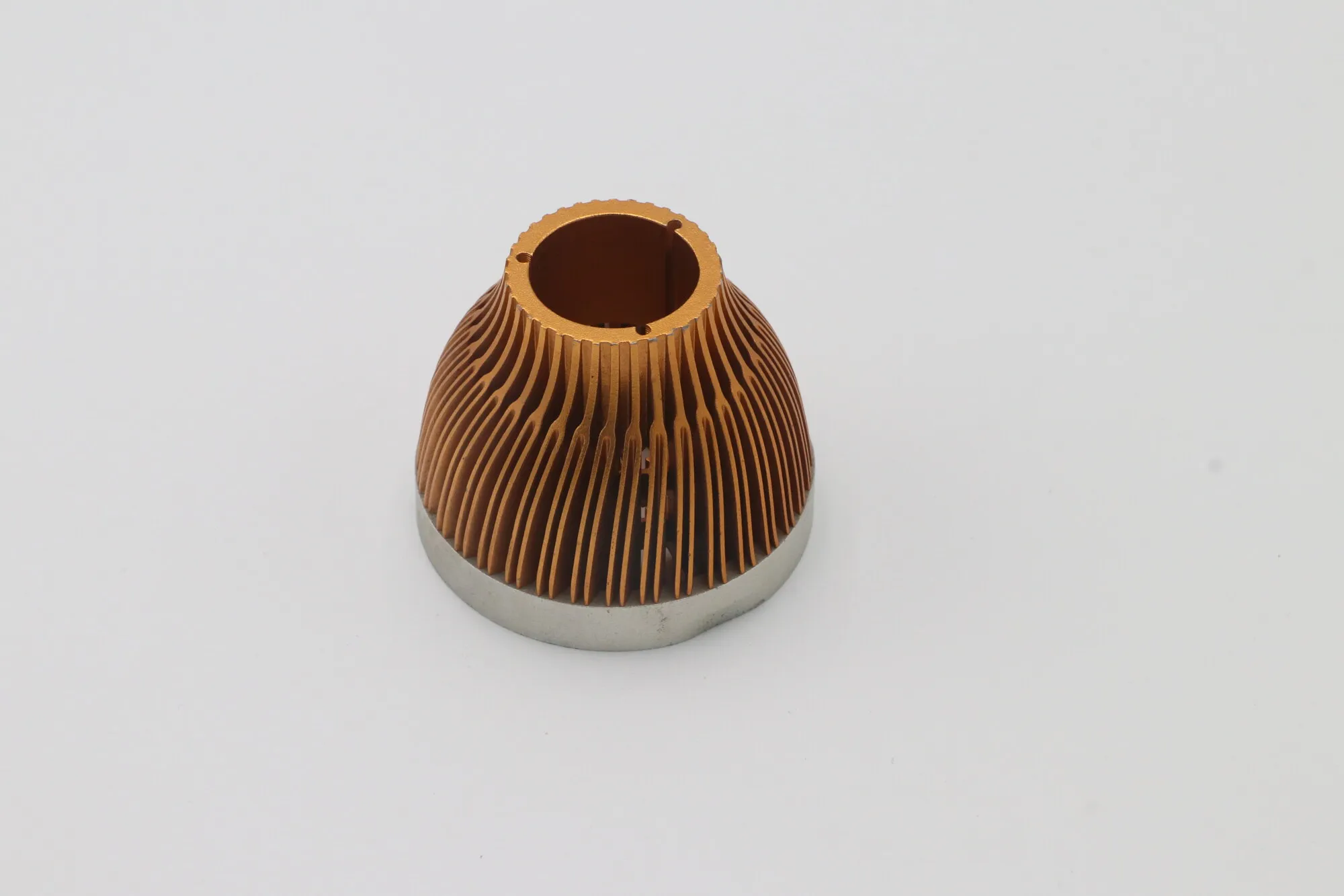
Internal bore for the driver, fins cut after the bore is established.
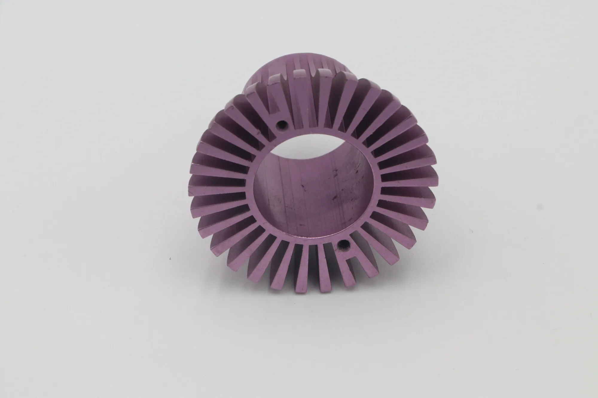
Fin root and tip condition — where chatter would show if it were present.
Parallel-fin sections pushed through a die, then cut, drilled and tapped to length. The die pays for the fin geometry once; after that the cost is in the machining.
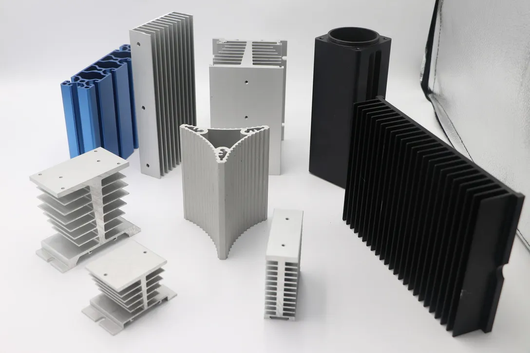
A spread of fin pitches and section depths from stock and custom dies, cut to length then drilled and tapped for mounting.
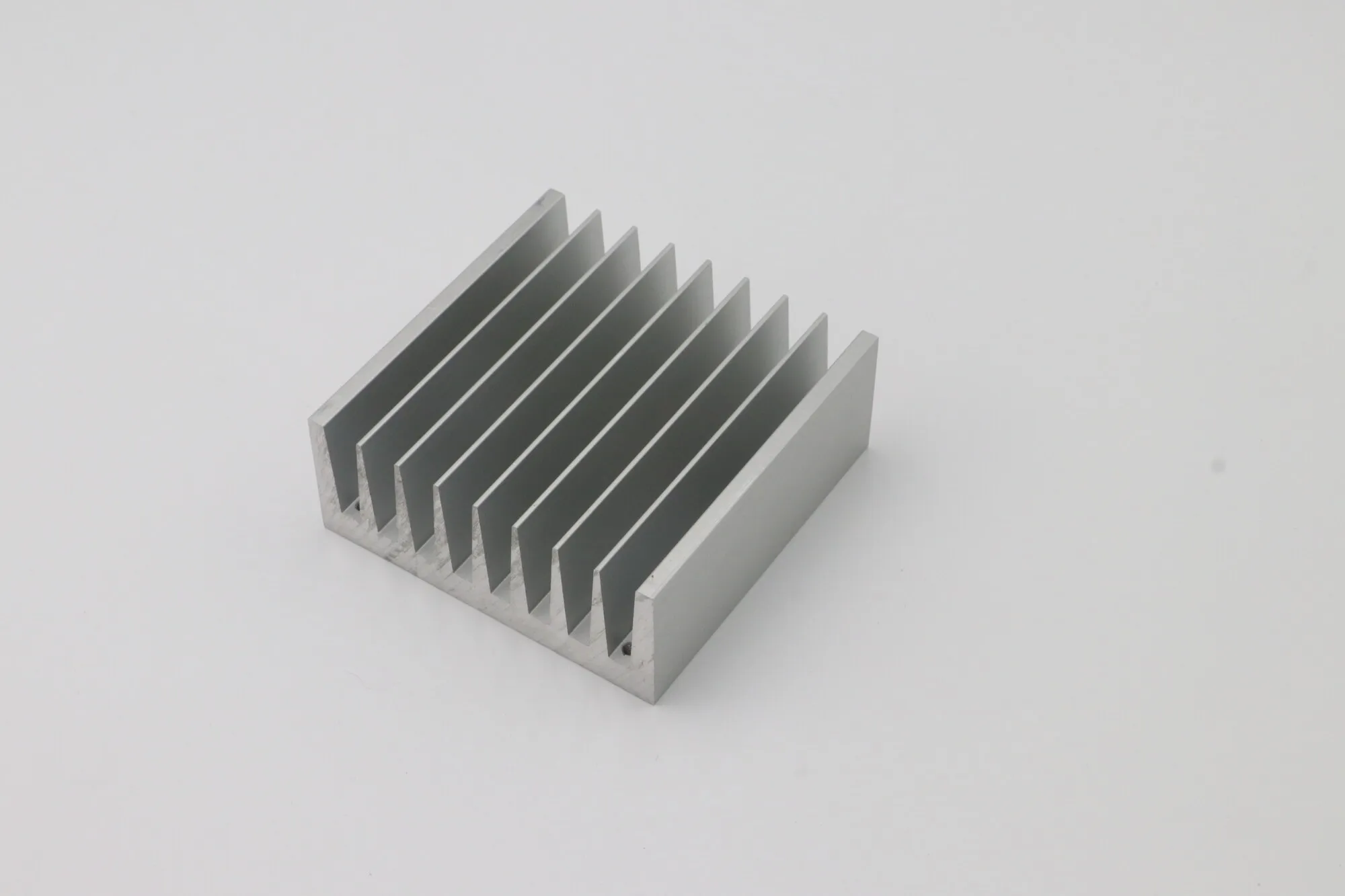
Mill-finish extrusion with a machined mounting face.
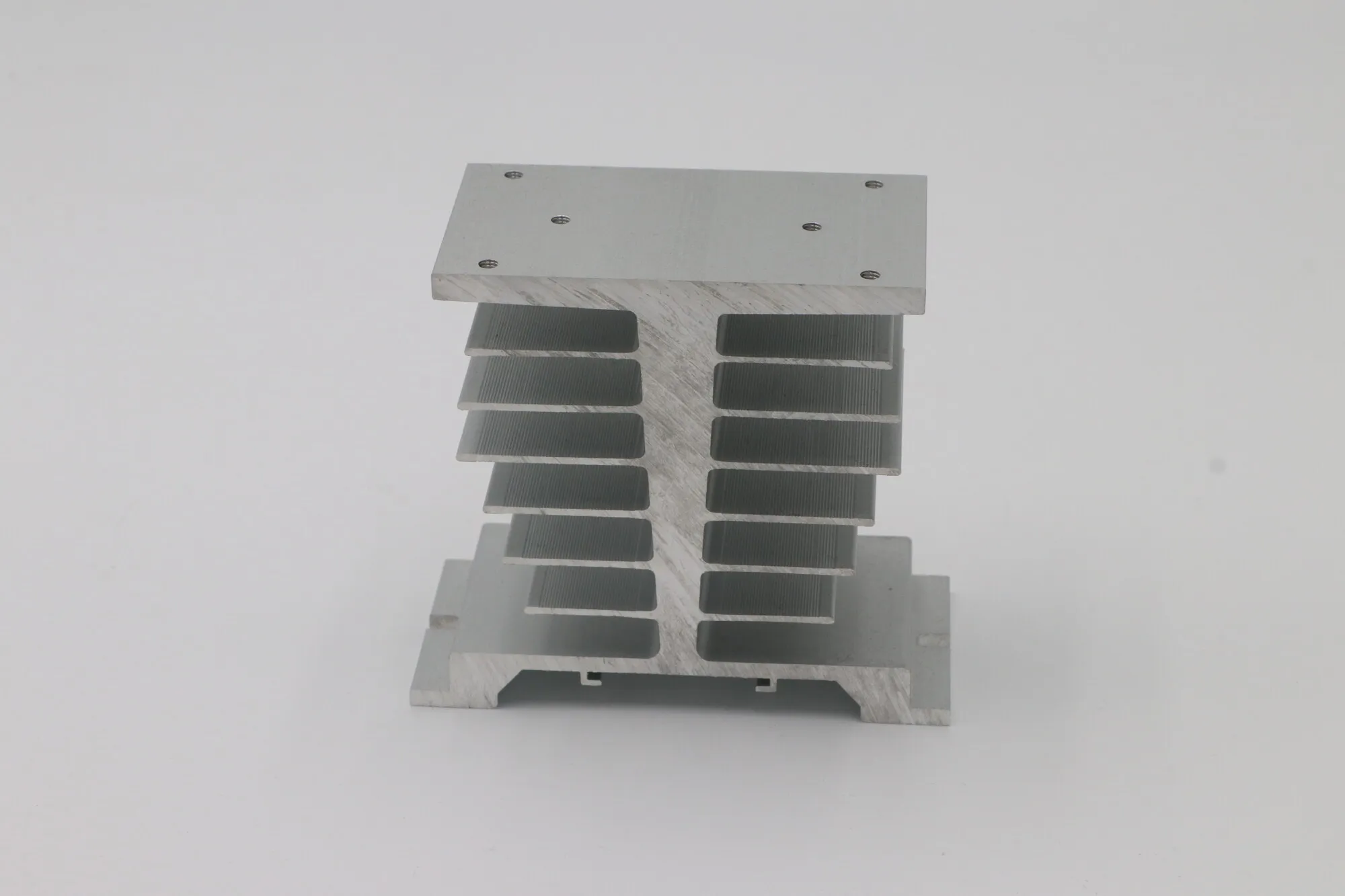
Deep fin stack, solid-state relay style, machined flat where the device clamps to it.
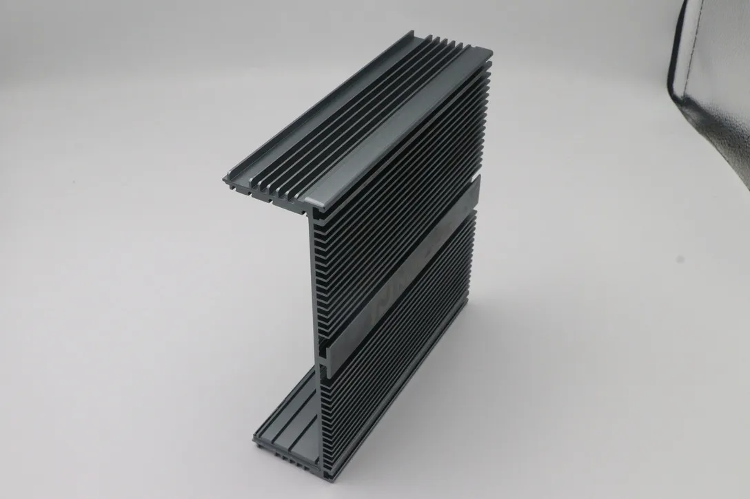
Black anodize for emissivity, with machined ends and slots.
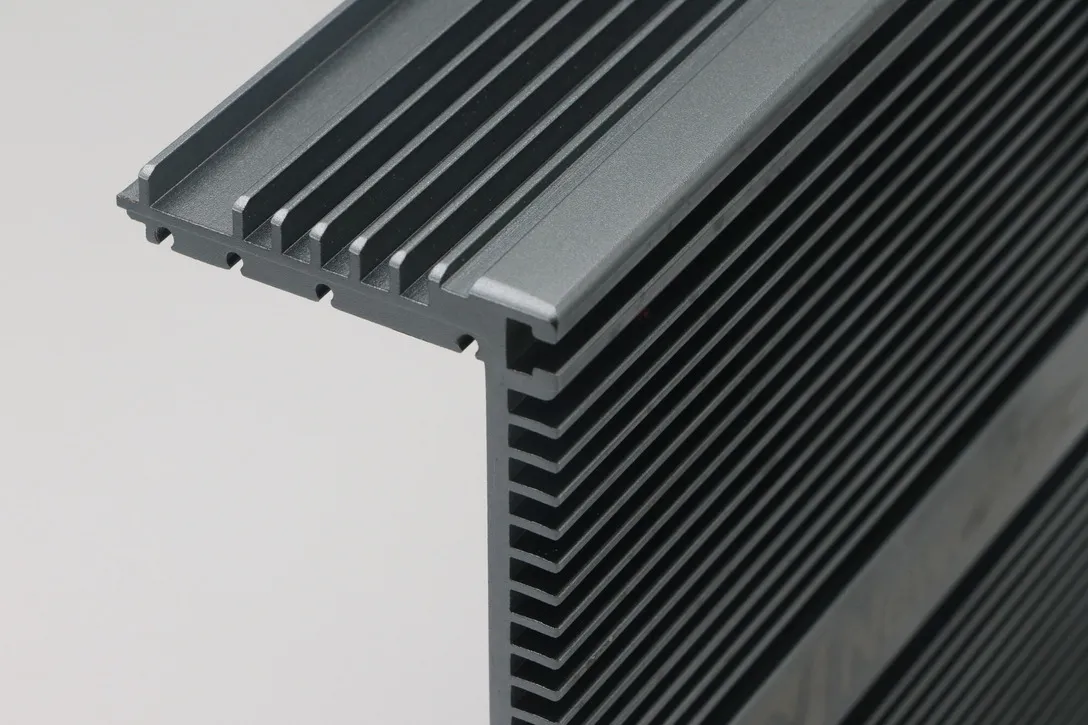
Close fin spacing — the limit is how evenly anodize reaches between them.
The numbers that matter are fin geometry, the flatness of the mounting interface, and how evenly the finish lands.
Fins down to around 1 mm with pitch to suit. Below that both cutter deflection and anodize penetration between fins become the limit rather than the machine.
Held flat across the device footprint, because thermal contact resistance there undoes the fin area you paid for.
Racking and agitation planned so color reaches between closely spaced fins evenly — the usual failure is pale roots on a dark part.
Costed both ways at enquiry. Tooling amortises quickly on parallel-fin sections; radial geometry generally has to be cut.
Black anodize raises emissivity and helps a part cooled by radiation in still air. On a forced-air part the finish is close to thermally irrelevant, so if the part is visible you can choose the color freely — tell us which case you are in.
Around 1 mm thick is routine, with pitch to suit the depth. Two things set the limit, and neither is the cutter's diameter: a tall thin fin deflects away from the tool and can chatter, and closely spaced fins are hard to anodize evenly because solution and agitation struggle to reach the root. If you need a specific thermal resistance rather than a specific geometry, tell us the target and we will suggest a fin design that will actually manufacture cleanly.
Mostly a volume question. Extrusion carries a die cost but then produces the fin cross-section almost free, so it wins clearly at production volumes and can include internal channels that would be costly to mill. Machining from billet has no tooling cost, so it wins for prototypes and low volumes, and it is the only route for radial fin geometry, which cannot be extruded. Send your annual volume and we will price both.
It depends on how the part sheds heat. Where radiation matters — a part sitting in still air — a black anodized surface has substantially higher emissivity than bare aluminum and does measurably better, which is why most heat sinks are black. Where a fan is moving air across the fins, convection dominates and the finish is close to irrelevant thermally. So on a forced-air part you can pick the color for appearance without penalty.
Yes, and it is worth calling out on the drawing. The interface between the device and the sink is often the largest single thermal resistance in the path, and it is set by flatness and finish across the device footprint — not across the whole part. Tell us where the device sits and we will hold flatness there specifically, which is both cheaper and more effective than asking for the entire face to be flat.
We machine to your geometry and can hold the fin dimensions and interface flatness it depends on, but we do not run thermal validation, so we cannot certify a °C/W figure. If you have a target thermal resistance, the practical route is for you to specify the geometry that meets it — or share the target and constraints and we will comment on which fin designs are manufacturable — and then verify performance on samples before production.
6063 for extruded profiles, since it extrudes well and takes a clean anodize, and 6061 where machined strength matters more than extrudability. Both conduct heat well enough for typical electronics cooling. If your application needs materially higher conductivity than aluminum — copper, for instance — tell us, because it changes both the machining and the cost significantly.
Send your drawing or STEP file with the material, quantity, fin geometry, mounting interface requirements and annual volume so we can cost extrusion against machining from solid.
Get a Quote