Sheet Metal Design & Engineering Guide
Design recommendations and general engineering considerations for custom sheet metal fabrication projects.
Get a Quote
Bend Design Guidelines
Bend geometry should be reviewed based on material, thickness, grain direction, bend angle, forming method, and tooling. The following points are preliminary DFM considerations rather than guaranteed manufacturing limits.
01Minimum Bend Radius
The required inside bend radius depends on material grade and temper, thickness, grain direction, bend angle, forming method, and tooling. Using consistent bend radii across a part can help simplify setup and improve forming consistency.
Minimum Flange Length
Minimum flange length depends on material thickness, inside bend radius, bend angle, die opening, and tooling. Insufficient flange support may prevent stable forming or reduce dimensional consistency.
Bend Relief Width
The width of a bend relief should provide adequate separation between the bent flange and adjacent material. The required width depends on material thickness, relief geometry, cutting process, and forming conditions.
Bend Relief Depth
The depth of a bend relief should extend beyond the bend deformation zone to help reduce tearing, bulging, or distortion near the end of a bend. The required depth depends on material thickness, inside bend radius, bend angle, relief geometry, and tooling.
* Important Note: Final bend and relief dimensions should be confirmed based on material, thickness, part geometry, forming sequence, and available tooling. Critical features should be reviewed before production.
Hole, Slot & Edge Clearance
Proper spacing between holes, slots, bends, and edges helps improve manufacturability and reduces the risk of deformation during fabrication.
Minimum Hole Diameter

Ø ≥ T
Using a hole diameter at least equal to the material thickness is a conservative starting point for standard laser-cut sheet metal features. Smaller holes may be feasible depending on the material, thickness, cutting process, and cut-quality requirements.

Preliminary reference for standard laser-cut holes.
Hole-to-Hole Distance

Project-Specific DFM Review
A is the clear edge-to-edge distance between adjacent holes. Required spacing depends on material thickness, hole size, cut quality, and the strength required in the remaining web.
Increase spacing where the remaining material carries load.
Hole-to-Bend Distance

Project-Specific DFM Review
B is measured from the bend reference shown to the hole centerline. Required clearance depends on the material, thickness, hole diameter, inside bend radius, bend angle, and tooling. Holes located within the bend deformation zone may distort during forming.
Confirm critical hole locations during drawing review.
Slot-to-Edge Distance

Project-Specific DFM Review
C is the clear distance from the slot edge to the part edge. Required clearance depends on material thickness, slot width, loading conditions, and the strength required in the remaining web.
Increase clearance for load-bearing or deformation-sensitive features.
*General Note: These are preliminary DFM references, not guaranteed manufacturing limits. Actual requirements may vary with material, thickness, feature size, part geometry, cutting method, bending sequence, and tooling. Critical features should be confirmed during drawing review.
Hardware Installation Guidelines
Proper hardware selection and placement can help improve fastening reliability, assembly fit, and manufacturing consistency.
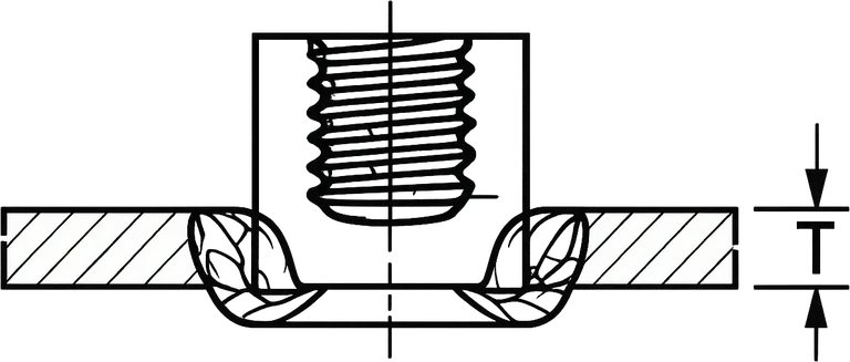
Self-Clinching Nuts
Select the fastener type and length only after confirming the manufacturer's minimum sheet thickness, permitted sheet hardness, mounting-hole size, and installation requirements.

Self-Clinching Studs
Allow sufficient clearance from sheet edges, bends, and adjacent features. Confirm the mounting-hole size, minimum sheet thickness, permitted sheet hardness, and installation requirements for the selected stud.
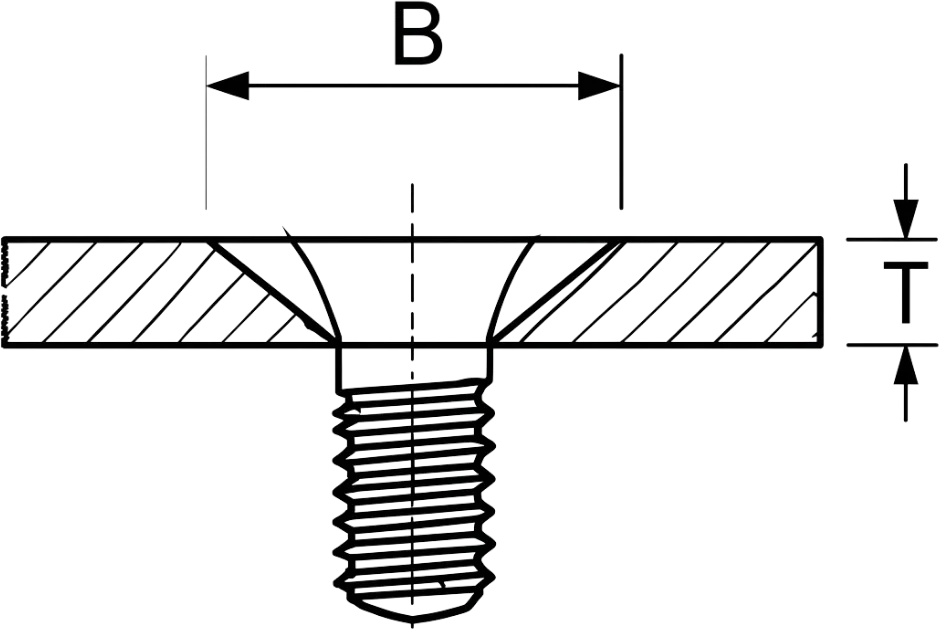
Countersunk Holes
Confirm that the material thickness, countersink angle, and major diameter leave sufficient material to support the fastener and avoid excessive thinning or distortion.

Hardware Edge Clearance
Use the fastener manufacturer's specified minimum distance from the mounting-hole centerline to the sheet edge for the selected fastener type and size. Clearance from adjacent bends should be confirmed separately based on the bend region and installation requirements.
* Note: Self-clinching hardware may include PEM® and equivalent fastening systems depending on project requirements. Hole size, sheet thickness, sheet hardness, edge distance, bend clearance, and installation requirements must be confirmed for the selected hardware.
Typical Manufacturing Tolerances
Standard tolerances for common sheet metal manufacturing processes. Values shown are typical reference tolerances and may vary depending on material, thickness, geometry, and equipment.
| Process / Feature | Typical Reference Tolerance | Notes |
|---|
| Laser Cutting | ±0.10–0.25 mm | Depends on material type, thickness, geometry, and cut-edge requirements. |
| Formed Sheet Metal Features | ±0.25–0.75 mm | Features across bends may be affected by bend angle, springback, and tolerance stack-up. |
| Bending Angle | ±1.0° | Tighter angular requirements should be reviewed based on material, thickness, bend length, and tooling. |
| Post-Machined Critical Features | Project-specific | Tighter tolerances may require secondary machining, controlled datum references, and drawing review. |
| Welding / Welded Assemblies | Project-specific, often ±1.0 mm or wider | Welding distortion, fixturing, heat input, and assembly stack-up may affect final dimensions. |
* General Note: These values are typical reference tolerances for sheet metal manufacturing and should not be treated as guaranteed limits. Actual tolerances depend on material, thickness, geometry, forming sequence, welding, finishing, and inspection requirements. Project-specific tolerances should be confirmed during drawing review.
Surface Finish Considerations
Surface treatments may affect dimensions, appearance, corrosion resistance, and assembly interfaces. Required allowances should be reviewed before production.
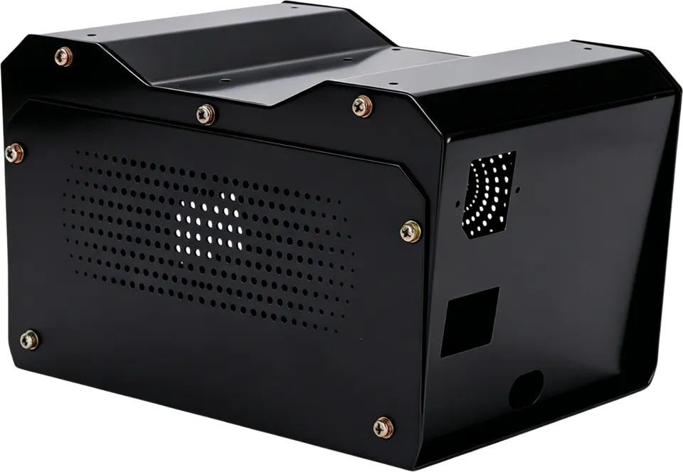
Powder Coating
Typical Thickness
60–120 μm
Coating buildup may affect tight-fitting features, threads, and mating surfaces. Required thickness depends on the coating system and project requirements.
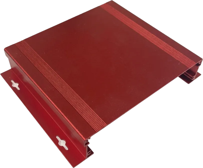
Type II Anodizing
Typical Reference Thickness
5–25 μm
Hard anodizing should be specified separately. Coating thickness and dimensional change depend on alloy and process requirements. Masking or dimensional allowance may be needed for threads and close-fitting features.
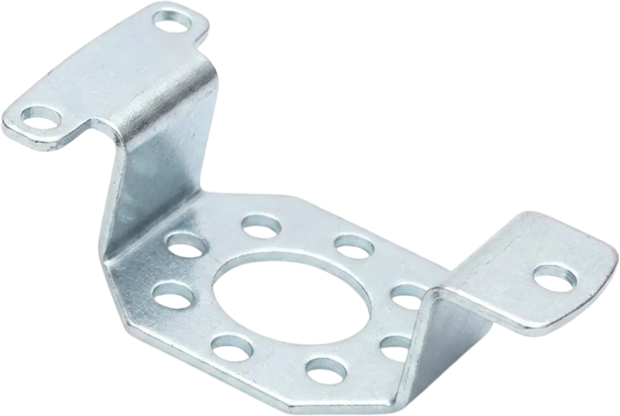
Zinc Plating
Typical Thickness
5–12 μm
Zinc plating can provide corrosion protection for suitable steel components. Required thickness depends on the specification, service environment, and dimensional requirements.
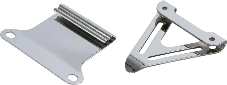
Passivation & Electropolishing
Stainless Steel Treatment
Passivation can improve corrosion resistance without depositing a conventional coating. Electropolishing smooths the surface through controlled material removal and may affect critical dimensions or edges.
DFM Recommendations
Simple design practices can help improve manufacturability, reduce avoidable cost drivers, and simplify production planning.

Simplify Bend Features
Use consistent bend radii and avoid tight reverse bends where possible.

Leave Space for Hardware
Provide adequate clearance for fasteners, tools and assembly operations.

Consider Finish Thickness
Account for coating or plating thickness on mating and critical surfaces.

Reduce Secondary Operations
Minimize tapping, rework and special tooling where standard solutions work.
Frequently Asked Questions
How do you handle tight tolerance features?
Our engineering team reviews tight-tolerance areas, evaluates suitable manufacturing methods, and identifies risk points related to deformation, fit, and rework before production.
Can you help review my design?
Yes. We provide design-for-manufacturing (DFM) reviews to improve manufacturability, identify cost drivers, and review assembly considerations.
What materials and thicknesses can you fabricate?
We work with common sheet metal materials such as aluminum, stainless steel, carbon steel, brass, and copper. Thickness range depends on the material and selected manufacturing process.
What surface finishes do you recommend?
Recommended finishes depend on material, application, and desired aesthetics. Common options include anodizing, powder coating, plating, and passivation. We can recommend suitable finishes based on corrosion protection, electrical requirements, appearance, and assembly needs.
Need Custom Sheet Metal Parts?
Our engineering team can review your drawings, evaluate manufacturability, and plan fabrication, hardware installation, surface finishing, inspection, and assembly requirements for your project.
- Design for Manufacturing (DFM) feedback
- Prototype and production quantities
- Material and finish selection support
- Integrated sheet metal, machining, and assembly services
Upload Your Drawing
Upload your drawing and provide the material, thickness, quantity, critical tolerances, surface finish, hardware, assembly, and inspection or documentation requirements.