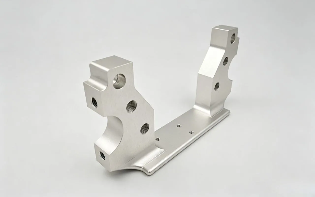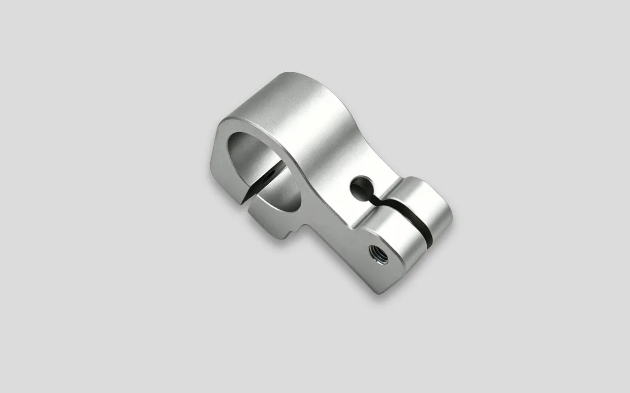
Hardcoat anodizing changes every coated feature on a CNC aluminum part. Pretreatment may remove material; anodizing then consumes aluminum below the pre-anodize surface while oxide grows outward. Bores, outside diameters, slots, threads, bearing seats, dowel holes, and sealing interfaces all shift. Planning that shift as a fixed percentage of nominal coating thickness is where most tolerance problems start.
What Hardcoat Anodizing Changes
Hardcoat anodizing — also called hard anodizing or hard anodic oxidation — is an electrolytic conversion process for aluminum. It produces a substantially different functional surface from decorative sulfuric-acid anodizing, paint, electroless nickel, chemical conversion coating, or plasma electrolytic oxidation. Our Type III hardcoat anodizing page covers what the finish is used for; this article covers what it does to your dimensions.
The process converts surface aluminum into aluminum oxide. A production route may include cleaning, etching, deoxidizing or desmutting, masking, anodizing, coloring, sealing, rinsing, and drying. Because pretreatment can remove metal, the complete approved route belongs in the dimensional plan — not just the anodizing step.
Under MIL-PRF-8625F with Amendment 2, Type III identifies a hard anodic coating, and the specification supplies default requirements where the contract, purchase order, or drawing is silent. Its default nominal Type III thickness is 0.002 in when no other value is stated. That figure is total coating thickness — not outward buildup — and it is not a universal recommendation for commercial hardcoat work. Masked surfaces, critical fits, sealing, color, local measurement locations, rack-mark restrictions, and final dimensional acceptance still need defining.
Coating Thickness Is Not Dimensional Growth
Three quantities have to be kept apart. Each is referenced to the metal surface immediately before anodizing, which may already differ from the CNC-machined surface after etching or other pretreatment:
- Total coating thickness is the full anodic layer, measured from the remaining aluminum substrate to the outer coating surface.
- Substrate consumption is the depth of aluminum converted below the surface present immediately before anodizing.
- Outward buildup is the portion extending beyond that pre-anodize surface.
Writing total layer thickness as T, substrate consumption as P, and outward buildup as B, the relationship is:
T = P + B
Anodic growth is driven by B, not by T. Net change from the CNC-machined dimension also includes whatever pretreatment removed. A roughly half-inward, half-outward split gets used for preliminary estimating, but it is not a process law, and production allowance should come from the specified finish and qualified process data.
Geometry then decides how buildup shows up in the final measurement:
- Buildup acts on both sides of an outside diameter and tends to increase it.
- Buildup on both bore walls tends to reduce the inside diameter.
- A slot or groove narrows when both walls are coated.
- A one-sided shoulder or surface location shifts by the buildup on that surface.
- A depth changes according to which floor and reference surfaces are coated or masked.
- Thread pitch diameter, crest, root, and flank clearances change together and cannot be treated as a flat-surface offset.
Coating thickness can meet its specification while a bore, a thread, or a fit fails its final requirement.
How Tight-Tolerance Features Are Affected
| Feature | Likely dimensional effect | Common DFM response | Inspection concern |
|---|---|---|---|
| Outside diameter | Buildup tends to increase it; pretreatment affects net change | Use a confirmed pre-anodize allowance, or mask the surface | Measure the finished diameter at defined locations |
| Precision bore or bearing seat | Buildup tends to reduce it; local growth may vary | Evaluate masking, a qualified pre-anodize size, or a permitted post-finish operation | Coating thickness alone does not prove the fit |
| Dowel or locating hole | Reduced clearance can prevent assembly or change repeatability | Define whether the hole is coated, masked, or finished to size afterward | Use a final dimension or a functional gauge tied to the assembly requirement |
| Slot, groove, or mating pocket | Opposing coated walls reduce available width | Include both coated surfaces in the tolerance budget | Check width, location, and measurement access after finishing |
| Thread | Pitch diameter and flank clearance change; friction and engagement may change with them | Decide explicitly whether to coat, mask, or use another validated thread strategy | Define the final gauging condition and mating-part assumptions |
| Sealing face | Texture, masking transitions, and local buildup affect contact | Coordinate coating extent, flatness, surface finish, and seal design | Inspect the finished sealing condition, not coating thickness alone |
| Grounding or contact area | Anodic oxide is electrically insulating | Mask or otherwise specify the conductive interface | Verify both mask location and required electrical function |
Precision bores, bearing seats, and locating holes
A bearing bore that measures acceptably after machining can be undersize after hardcoat. Dowel holes and locating features behave the same way. Masking keeps a feature free of anodic coating, but whether it preserves the machined surface depends on which pretreatment steps the mask covers. A controlled post-finish machining or honing operation is sometimes possible, at the cost of exposing aluminum and disturbing adjacent coating.
The drawing should identify the final fit, the coating condition, and the acceptance method, and any pre-anodize compensation has to be realistic for the finishing route actually selected.
Threads
Hardcoat changes more than a thread’s major or minor diameter. Buildup on the flanks changes pitch diameter and engagement, coating at crests and roots alters local geometry, and the finished surface changes friction and tightening behavior. A coated thread has to be evaluated with its mating material, lubrication, required preload, assembly frequency, and service environment.
There is no universal pre-anodize allowance for aluminum threads. Coating, masking, chasing, and insert strategies are all application-dependent. Cutting or chasing after anodizing exposes aluminum and may disturb the coating around it. State whether functional gauging applies after all finishing, and if coating or lubrication changes friction, revisit the torque–preload relationship rather than assuming the original torque still holds.
Sealing and electrical interfaces
Hardcoat does not automatically create a good fluid-sealing surface. Texture, flatness, defects, mask transitions, seal compression, and the counterface all still matter. Nor should an anodized surface be assumed to provide a dependable grounding path — conductive areas need a defined treatment or mask plan.
Why Buildup Is Not Perfectly Uniform
An anodizing callout does not guarantee identical thickness or growth on every surface. Local formation is influenced by alloy and temper, current-density distribution, orientation, racking, electrical contact, edges, recesses, blind holes, slots, masking boundaries, pretreatment, and circulation.
Review sharp edges and thin or asymmetric sections with the finishing source, since edge coverage, racking, pretreatment, and coating formation all affect dimensional repeatability. No universal radius or wall threshold applies.
A requirement for “uniform coating thickness” says nothing about what is achievable inside a deep bore or a shielded passage. Define the critical measurement locations, and discuss inaccessible areas before quotation.
Alloy and Pretreatment Affect the Result
6061, 6082, 7075, and cast alloys are all hardcoat candidates, and none of them produce identical results. Composition, temper, microstructure, prior processing, and surface condition influence appearance, roughness, defects, corrosion response, and repeatability. High-silicon cast and higher-copper alloys need process-specific review; the alloy designation alone does not predict the finish. 6061 vs 7075 covers how the two most common grades differ under anodizing.
Etching and other alloy-dependent pretreatment steps remove or alter the base surface, so a pre-anodize dimension cannot be calculated from buildup while ignoring the approved process sequence.
Where appearance matters, separate cosmetic requirements from functional ones and account for alloy, preparation, coating thickness, sealing, and lot variation. Sealing or impregnation should be chosen for the required balance of corrosion resistance, wear, friction, cleanliness, and any subsequent bonding or lubrication — neither is a default.
When Masking Is the Better Choice
Masking earns its cost when coating would compromise a fit, an electrical connection, a seal, or a downstream operation, particularly where final size matters more than local wear protection.
A mask boundary has width and process-transition effects; it is not mathematically sharp. Plugs need access, rack contacts need an approved location, and uncoated features behave differently in corrosion and wear.
A workable drawing identifies coated and uncoated surfaces, locates critical mask boundaries from a stable datum, and states the final dimensions of masked features. “Mask critical areas” leaves the decision to someone who cannot make it.
Build a Tolerance Budget Around the Final Part
The drawing and RFQ should distinguish four conditions:
- the machining dimension before anodizing;
- the expected change from pretreatment and coating;
- the required final dimension after all finishing;
- the inspection method and acceptance condition.
The budget may take in machining variation, pretreatment removal, buildup, masking, measurement uncertainty, and temperature. Tightening the machining tolerance cannot control an unqualified finishing process, and it adds cost without touching the dominant source of variation.
Establish capability for the actual alloy, geometry, coating, route, supplier, racking, and measurement method. On a new design, samples or a controlled first article are worth more than an allowance borrowed from an unrelated part.
Inspection After Hardcoat Anodizing
Coating-thickness measurement, dimensional inspection, functional gauging, and performance testing answer four different questions.
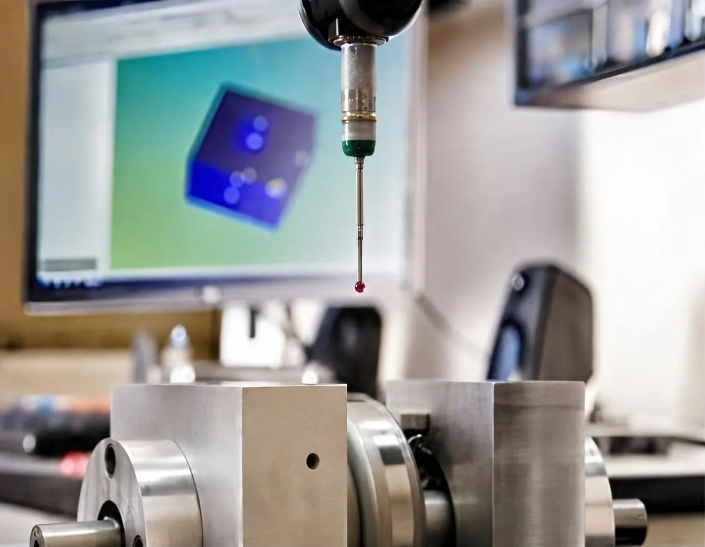
ASTM B244-09(2021) describes nondestructive eddy-current measurement of nonconductive coatings on nonmagnetic base metals, which suits anodic coatings on aluminum. Its suitability depends on calibration, substrate conductivity, probe access, curvature, edges, roughness, and measurement location. A reading taken on an outside face establishes nothing about thickness inside a small bore, and it does not prove the bore dimension.
Final inspection needs a method suited to the feature in its finished condition. A bearing seat may need direct measurement, an assembly interface may justify functional gauging, and coating performance may require separate tests. Define sampling, records, and acceptance in the drawing, purchase order, or inspection plan.
Common Drawing Mistakes
- Calling out “Type III anodize” without identifying the governing specification, or leaning on a specification default when the application needs a different thickness, sealing condition, mask plan, color, or final dimensional result.
- Applying a tight tolerance without stating whether it applies before or after anodizing.
- Coating a bearing bore, dowel hole, slot, or thread without allowing for the final dimensional change.
- Specifying a mask without defining its side, boundary, datum, or transition.
- Requiring grounding through a surface that is fully anodized.
- Treating color as independent of alloy, preparation, and coating condition.
- Tightening the CNC machining tolerance without confirming finishing capability.
- Measuring coating thickness but omitting final dimensional or functional acceptance.
MIL-PRF-8625F with Amendment 2, SAE AMS2469L, and ISO 10074:2021 can all govern hard anodic coatings when contractually invoked. They are not interchangeable, and none of them replaces the part drawing. MIL-PRF-8625 is not mandatory for ordinary commercial components merely because the finish is called hardcoat anodizing.
What to Include in the Drawing or RFQ
Give the supplier:
- aluminum alloy, temper, and any material certification requirement;
- the governing coating specification, including revision where that is contractually controlled;
- coating type, class or color, and required thickness or range;
- whether coating thickness is nominal, minimum, or a range, and whether a specification default is acceptable;
- sealed, unsealed, dyed, impregnated, or other post-treatment condition;
- CAD model and controlled drawing with datum structure;
- which dimensions apply before anodizing and which are required after all finishing;
- identified press fits, slip fits, bearing seats, bores, dowel holes, threads, slots, sealing faces, and electrical contacts;
- coated and masked surfaces, mask boundaries, acceptable contact or rack-mark locations, and any cosmetic zones;
- mating-part materials and conditions, fits, clearances, assembly conditions, preload, and functional-gauge requirements;
- coating-thickness measurement locations, including the approved method for inaccessible internal features, and the final dimensional inspection method;
- performance tests, sampling level, inspection records, certificates, and documentation requirements;
- service environment, temperature, wear, corrosion, friction, cleanliness, and electrical requirements;
- prototype, batch, and annual quantities.
With that in hand, machining, finishing, and inspection planning can all address the same finished-part requirement before pricing and production decisions are fixed. What to include in a CNC machining drawing and RFQ covers the rest of the package.
Specify the Finished Part, Not the Coating
The dimension that matters is the one the part leaves with. Coating thickness is a process characteristic; the fit, the thread, and the seal are the requirement. A drawing that states both — and says which applies before finishing and which after — is the one that gets made correctly the first time.
Frequently Asked Questions
How much does hardcoat anodizing change a bore diameter?
Buildup on both walls tends to reduce a coated bore, but no universal percentage converts nominal thickness into final diameter. Account for pretreatment and qualified process variation, then specify the final bore and the inspection method.
Should bearing bores be masked before hardcoat anodizing?
Consider masking when preserving the fit matters more than coating the bore. The decision still depends on wear, corrosion, load transfer, mask location, assembly, and whether a qualified allowance can reach final size.
Does MIL-PRF-8625 Type III define the final part dimensions?
No. MIL-PRF-8625 requires coated parts to meet the dimensional requirements of the applicable drawing, but it does not create those dimensions. Type III has a default nominal coating thickness of 0.002 in where the contract, purchase order, or drawing specifies nothing else. Critical post-finish dimensions, masking, fits, local measurement locations, and functional inspection still have to be defined in the product requirements.
References
- DLA ASSIST — MIL-PRF-8625F, Amendment 2, Anodic Coatings for Aluminum and Aluminum Alloy
- SAE International — AMS2469L, Hard Anodic Coating on Aluminum and Aluminum Alloys
- ISO 10074:2021, Anodizing of Aluminium and Its Alloys — Specification for Hard Anodic Oxidation Coatings
- ASTM B244-09(2021), Measurement of Thickness of Anodic Coatings with Eddy-Current Instruments