The decision is not how many decimal places to put on the drawing. It is which variation can cause failure, which datum relationship controls that variation, and how the requirement will be manufactured and verified. A useful CNC machining review starts from function, not from a default decimal place.
Tight Tolerances Should Follow Function
A drawing can pass every individual dimension check and still produce a part that will not assemble or operate. A bearing bore sits within its size limits but misaligned with the second bore. A mounting face meets its thickness tolerance yet fails to support a seal, because nothing controls its form or orientation. A clearance-hole pattern is machined to needless precision while the pilot diameter — the feature that actually locates the assembly — carries a loose limit.
Start with the failure condition:
- What does the feature locate, support, guide, seal, retain, or clear?
- What is the mating feature, and what are its limits?
- Which surfaces or axes establish the part in the assembly?
- Does function depend on size, form, orientation, location, profile, runout, surface texture, or some combination?
- Is the requirement evaluated before or after heat treatment or surface finishing?
- Can the proposed process and inspection method verify it consistently?
A feature that affects function needs an appropriate control. That is not the same as the narrowest possible tolerance — design clearance, compliance, adjustment, or a different locating scheme is often the more robust answer.
Size Is Not the Same as Geometric Control
“Tight tolerance” tends to hide the real requirement. These controls answer different questions:
| Control type | What it controls | Functional question | Common drawing problem |
|---|---|---|---|
| Size | Limits of a feature of size — a diameter, width, or thickness | Will the mating features produce the required clearance, transition, or interference? | Tightening size when alignment or form is the actual concern |
| Form | Shape of an individual feature: straightness, flatness, circularity, cylindricity | Will the feature support, rotate, or seal as intended? | Assuming a size tolerance always provides the needed form control |
| Orientation | Angular relationship to a datum reference, such as parallelism or perpendicularity | Will the surface or axis have the required attitude in the assembly? | Using a plus/minus angle without a functional datum structure |
| Location | Position of a feature or pattern relative to a datum reference frame | Will holes, pins, bores, or interfaces assemble in the correct relationship? | Independent coordinate tolerances that obscure the pattern requirement |
| Profile | Permitted boundary variation of a line or surface | Does a contour fit, clear, or seal as required? | Over-dimensioning a contour with many separate coordinates |
| Runout | Permitted variation of a surface relative to a datum axis | Will a rotating-related surface run true to the functional axis? | Calling out “runout” without the surface, datum axis, or circular versus total |
| Surface texture | Specified characteristics of the surface at the applicable scale | Is the surface suitable for bearing support, sliding, sealing, coating, or appearance? | Treating a roughness value as a substitute for form, waviness, or dimensional control |
The governing drawing system matters here. Under ASME Y14.5, size limits can impose a form boundary on a regular feature of size through Rule #1 unless an exception applies; ISO GPS applies its own default and independency rules. The two are not interchangeable. State the governing standard and edition on the product definition, then apply its rules consistently. ASME Y14.5-2018 (R2024) and ISO 1101:2017 are useful starting points, each within a broader framework.
CNC Machining Tolerances for Functional Features
Bearing seats and precision bores
A bearing-seat requirement starts with the selected bearing and its operating condition. Fit selection depends on bearing type and internal clearance, load direction relative to each ring, shaft and housing material, wall stiffness, temperature, assembly method, and whether the bearing will have to come out again.
Seat diameter is only part of the interface. Depending on function, the drawing may also need to control bore form, the shoulder that locates the ring axially, the relationship between bearing axes, the runout of a rotating-related surface, and surface texture. Those controls should not be stacked automatically — aim for the smallest nonconflicting set that describes the functional interface.
Bearing-manufacturer recommendations are application-dependent. Confirm the fit and seat requirements against current guidance for the actual bearing rather than assigning one bore tolerance to every bearing application.
Locating features and datum interfaces
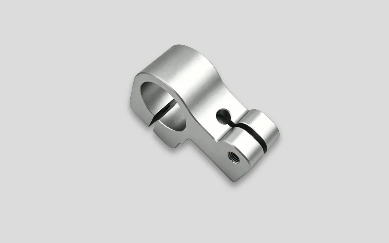
Dowel holes, locating pins, pilots, shoulders, and mounting faces are what make assembly repeatable. Decide first which features locate the part and which merely clamp it. A pilot may establish radial location while a planar mounting feature establishes axial location and orientation; ordinary bolt-clearance holes clamp without locating. Fitted fasteners are a different design decision and should be identified as such.
In GD&T, the physical surface or bore selected on the part is a datum feature; the datum is the theoretically exact reference established from that feature under the governing rules. Inspection uses a physical or mathematical datum feature simulator to establish the datum reference frame. Datum precedence and constrained degrees of freedom should reflect how the part functions, not which surfaces are easiest to probe. Datum targets may be appropriate where full-surface contact does not represent the assembly.
Manufacturing workholding and inspection do not have to use identical hardware, but both have to establish valid references to the product definition. Otherwise a feature passes in one setup and fails in another.
Press, transition, and controlled-clearance fits
A fit is a relationship between mating features. The permitted hole and shaft limits set the nominal clearance or interference range, while actual assembly behavior also depends on form, orientation, surface texture, compliance, coating, and temperature.
Thin hubs expand during insertion and thin housings distort. Dissimilar materials change the fit across the service-temperature range. Plating or anodizing alters the final interface. Define the mating component, materials, assembly method, service condition, and whether the limits apply before or after finishing.
ISO 286-1:2010 provides terminology and a code system for tolerances and fits on cylindrical features and two parallel opposite surfaces. It does not control form, orientation, or location, and it does not choose the correct fit for the application.
Sealing interfaces
Static and dynamic seals place different demands on machined features.
For a static face or radial seal, groove geometry, mating size, surface texture, edge condition, and the form or orientation of the sealing interface govern compression and leakage. For a dynamic shaft seal, the controlled shaft surface, axis relationship, runout, texture, lead, speed, pressure, media, and installation condition all come into play.
Use the seal manufacturer’s current design guidance or the applicable product standard. Generic groove dimensions are not enough without the seal type, material, pressure direction, temperature, motion, media, and installation method. On an ASME Y14.5-2018 drawing, avoid the obsolete generic callout “concentricity” — specify the needed axis location or orientation, or circular or total runout of a defined surface relative to a defined datum axis.
Aligned bores, shafts, and drive interfaces
Two bores can meet their individual size limits and still prevent a common shaft from passing through or turning freely. Their axes need controlled location and orientation from a shared datum structure. A runout control may suit a specified surface related to rotation, but it is not a generic substitute for bore-axis alignment.
Motor, gearbox, actuator, and spindle interfaces usually divide location and clamping among several features: a pilot locates radially, a mounting face sets axial position and orientation, and a bolt pattern clamps the joint. The functional controls follow that division — pilot fit, mounting-face orientation, bore-axis location, runout of a particular journal or face. None of it implies that every bolt hole needs precision boring.
Mating faces and hole patterns
A mounting face can satisfy its thickness limits and still be unsuitable if flatness or orientation affects support, alignment, or sealing. Hole patterns fail the same way: independent coordinate limits let each hole pass while consuming the available assembly clearance in an unfavorable direction.
Position tolerancing tied to functional datum features communicates a pattern requirement far more clearly. Under the selected standard, basic dimensions establish theoretically exact geometry and the geometric tolerance defines the permitted variation. Material-boundary modifiers or functional gaging help in some assembly conditions — apply them only when their rules and functional consequences are understood.
Thin-wall and distortion-sensitive features
A close finished dimension does not stop a flexible part from moving. Stock removal redistributes residual stress, clamping temporarily forces a wall into position, heat treatment and some finishing processes change geometry, and the part moves again after unclamping.
A DFM and engineering review should cover roughing and finishing sequence, balanced stock removal, material form and temper, workholding force, stabilization time, and the stage at which final inspection happens. For a nonrigid part, the drawing or inspection plan may also need to define whether acceptance is in the free state or a restrained condition, including supports, contact locations, and applied force. Why thin-walled parts distort after unclamping goes through the mechanisms.
Features affected by anodizing, plating, and other finishes
Finish-related dimensional change depends on the process. Electroplating deposits material on the substrate. Anodizing converts part of an aluminum surface into oxide, with the coating developing both into and outward from the original surface. Conversion coatings, paint, and other finishes follow their own mechanisms.
Total coating thickness is therefore not automatically equal to outward dimensional growth, and a single-surface change is not the same as the total change across a diameter. Substrate, alloy, pretreatment, feature geometry, specified coating, masking, and local process distribution all affect the result, so no universal growth ratio applies. This matters most when hardcoat anodizing meets tight-tolerance aluminum parts.
For a critical bore, shaft, seal groove, thread, or datum feature, the drawing should state whether the requirement applies before or after finishing. It may also need to define:
- finish type, class or thickness requirement, and controlled area;
- masking boundaries and acceptable transition zones;
- rack or electrical-contact restrictions where relevant;
- allowance for the selected process;
- post-finish machining, and how exposed substrate will be treated;
- final inspection stage and method.
Threads need the same clarity. State whether they are masked or coated and when they are accepted. Post-finish chasing or material removal should not be assumed permissible — it may remove the specified protective layer or change thread acceptance.
Features That Can Often Use General Tolerances
General tolerances usually suit non-mating exterior dimensions, clearance pockets, access openings, weight-reduction pockets, non-locating clearance holes, and nonfunctional chamfers. They may also cover overall dimensions that do not control packaging or assembly.
The classification is conditional, though. A pocket becomes functional the moment it controls stiffness, balance, minimum wall thickness, or tool access. An exterior surface becomes critical inside a fixed envelope. A chamfer may guide assembly or protect a seal. Use general tolerances only after confirming that they are both functionally sufficient and reasonable for the process.
The drawing has to state the applicable general-tolerance system or title-block requirements. ISO 2768-1:1989, for example, provides general tolerance classes for eligible linear and angular dimensions without individual indications. It remains published but is marked by ISO as “to be revised,” so confirm its status and applicability when a drawing is released. ISO 2768-2:1989 has been withdrawn and should not be cited as a current general geometrical tolerance standard.
Why Unnecessary Precision Changes the Quotation
Cost follows the process and verification plan required to meet the drawing, not the printed decimal places. Geometry, material, access, feature size, quantity, setup strategy, surface condition, and demonstrated process capability all feed into it.
A close requirement may call for a different tool or finishing operation, additional passes, tighter tool-wear control, a more stable setup, or preservation of related features in one operation. Inspection may need controlled fixturing, defined measurement force, temperature evaluation, more capable equipment, additional reporting, or a different sampling plan.
Ambiguity has a price too. If every dimension carries the same close tolerance, the supplier has to quote against those requirements, disclose assumptions or proposed deviations, ask for clarification, or decline the work. Different suppliers then quote differently because they assumed different datum setups, finish conditions, inspection methods, sampling, or acceptance rules — one of the main reasons quotes vary for the same part.
Identifying critical-to-quality features makes a quotation easier to interpret. It does not relax acceptance; it tells manufacturing and inspection where the functional risk is concentrated.
Tolerance Stack-Up Is an Assembly Problem
Individually acceptable components still create an unacceptable assembly when variation accumulates through a dimension chain.
Take a simplified one-dimensional example: a motor, an adapter plate, and a driven component. If signed offsets A, B, and C act along the same axis, the assembled offset is the algebraic chain A + B + C. A real axis-alignment problem has x and y components, angular effects, clearances, and datum shifts, and those have to be treated as vectors or inside a suitable three-dimensional tolerance model.
Worst-case analysis evaluates the least favorable permitted combination and suits assemblies that must work at the specified limits. Statistical analysis supports a different allocation only when its assumptions hold — stable and measured processes, representative data, suitable distribution models, known centering or bias, correlation between contributors, drift control, and an accepted risk policy. A statistical prediction does not change individual drawing conformance unless the product definition or contract explicitly permits it.
Before choosing a method, identify the closed functional loop, the assembly sequence, the datum structure, and any adjustment or compliance in the joint.
A Practical Sequence for Assigning Tolerances
- Define the function. State what the feature locates, fits, seals, guides, supports, clears, or transfers.
- Identify the mating interface. Review both components, their material conditions, and their permitted variation.
- Establish functional datum features. Set datum precedence and constrain the required degrees of freedom in a way that represents assembly.
- Choose the correct control. Decide whether function depends on size, form, orientation, location, profile, runout, or surface texture.
- Account for process state. Identify heat treatment, coating, masking, post-processing, and whether acceptance is before or after finishing.
- Review manufacturing feasibility. Consider access, setups, workholding, wall flexibility, tooling, and production quantity.
- Define verification. Align the inspection method, datum simulation, restraint, sampling, reporting, and acceptance rule with the drawing intent.
- Confirm repeatability. A drawing tolerance is a product requirement; process capability needs a stable process, representative data, and an adequate measurement system. One successful part is not capability evidence.
Inspection Must Match the Drawing Intent
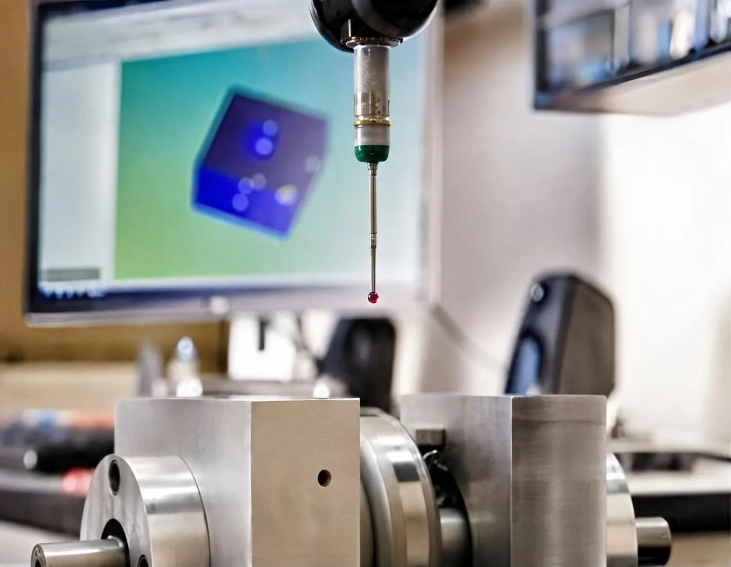
Close tolerances are incomplete without a credible inspection and quality-control plan. Buyer and supplier may need to agree on the inspection stage, datum simulation, part restraint, measurement force, sampling, report format, traceability, and the decision rule to use when measurement uncertainty is significant near a specification limit.
Temperature affects dimensional verification as well. ISO 1:2022 defines the standard reference-temperature framework for geometrical and dimensional properties. That does not mean every part must be measured in one identical room condition — it means part and instrument temperatures, material coefficients of thermal expansion, thermal equilibrium or correction, and the resulting uncertainty should be considered when they are significant relative to the requirement.
For ISO GPS specifications, ISO 14253-1:2017 addresses conformity decisions accounting for measurement uncertainty. The contractual inspection and acceptance rules still have to be agreed for the actual project.
What to Include in a CNC RFQ
Before quotation, provide or confirm:
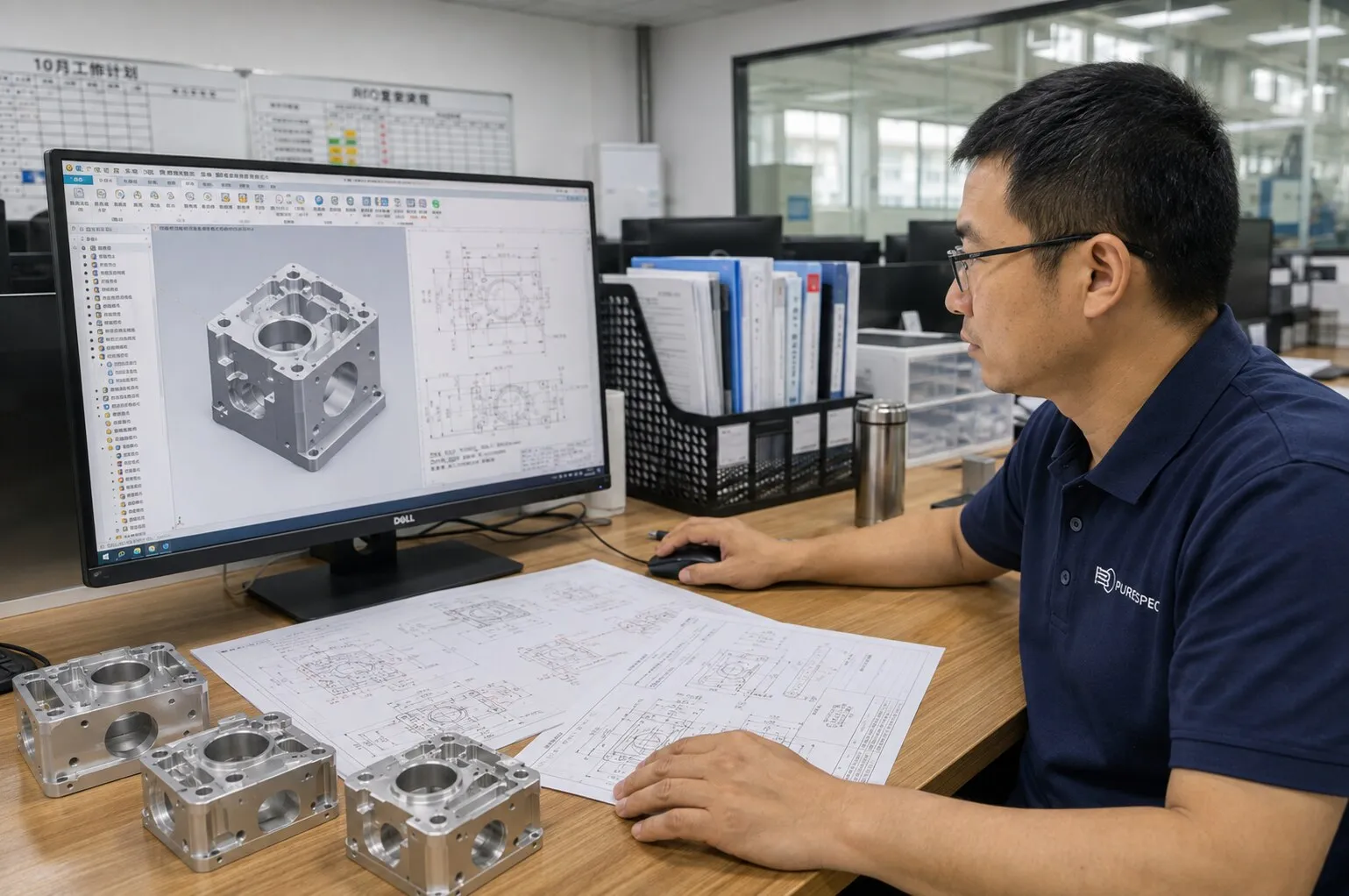
- 3D CAD and the controlled 2D drawing, with units and product-definition authority identified;
- material grade, product form, temper or condition;
- prototype and expected production quantities;
- drawing and model revision levels;
- identified critical-to-quality features, and the functional reason for each;
- mating-part dimensions, fit designation, or interface specification;
- finishing, masking, heat-treatment, and pre- or post-finish requirements;
- the governing drawing and GD&T standard, including edition;
- inspection method, sampling, reporting, first-article, traceability, and documentation expectations where applicable;
- acceptance or measurement-decision requirements where uncertainty may affect conformity.
If the CAD model and drawing conflict, resolve the discrepancy before release. If a fit is critical, sending only one side of the interface leaves the supplier to guess. What to include in a CNC machining drawing and RFQ covers the full package.
Control the Features That Make the Part Work
Effective tolerances describe functional relationships rather than a general preference for precision. Apply specific controls to fits, locating features, aligned axes, sealing surfaces, and the other interfaces where variation changes performance — and let stated general tolerances carry everything else.
Frequently Asked Questions
What is a standard CNC machining tolerance?
There is no single standard tolerance for every machined feature. Use the drawing's stated general tolerances and its feature-specific requirements, then confirm feasibility for the geometry, material, process, finish, quantity, and inspection method.
Does every dimension need an individual tolerance?
No. Every requirement needs an acceptance basis, but eligible noncritical dimensions can be covered by a clearly stated general-tolerance system. Basic dimensions, reference dimensions, and directly toleranced dimensions each serve a different purpose under the governing standard.
When should GD&T be used instead of coordinate tolerancing?
When the functional requirement is better expressed through form, orientation, location, profile, or runout with a coherent datum structure. Form tolerances generally do not reference datums; orientation, location, runout, and some profile applications do.
Why do tighter tolerances increase CNC machining cost?
They can change the machining, setup, tooling, workholding, inspection, reporting, and rework risk. The effect depends on the particular feature and process, so a universal cost multiplier is not credible.
Should tolerances apply before or after anodizing or plating?
The drawing should state the required condition for every finish-sensitive feature. Bores, shafts, threads, seal interfaces, and datum features may need process allowance, masking, or approved post-finish machining followed by final verification.
References
- ASME Y14.5-2018 (R2024), Dimensioning and Tolerancing
- ISO 1101:2017, Geometrical tolerancing
- ISO 5459:2024, Datums and datum systems
- ISO 286-1:2010, ISO code system for tolerances on linear sizes
- ISO 2768-1:1989, General tolerances for linear and angular dimensions
- ISO 1:2022, Standard reference temperature for geometrical and dimensional properties
- ISO 14253-1:2017, Decision rules for verifying conformity or nonconformity