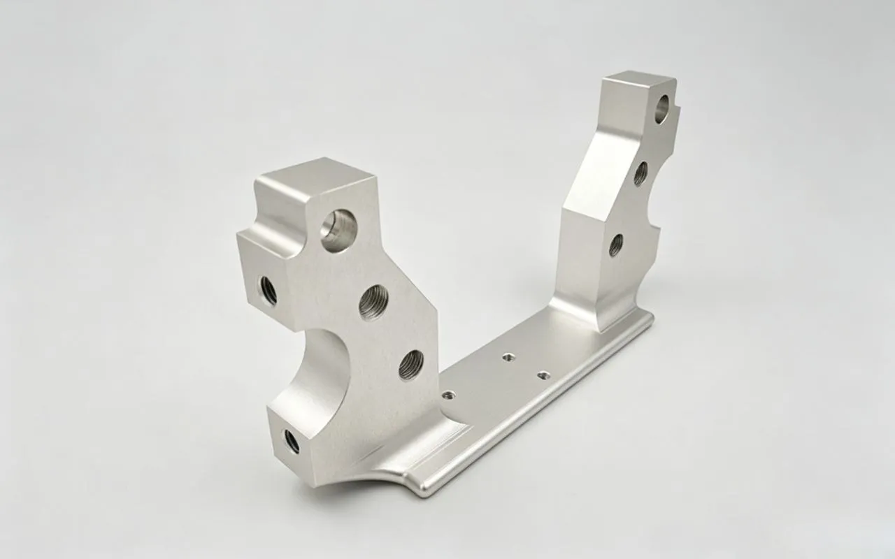
A thin housing, frame, or plate measures fine in the fixture, then bows, twists, opens, or changes dimension the moment the clamps come off. That is not evidence of an inaccurate machine. Cutting-load wall deflection, tool deflection, fixture-induced elastic recovery, residual-stress redistribution, thermal effects, and outright damage all produce similar symptoms.
Before assigning a cause, establish the state in which the part was machined and the state in which it was measured. Clamped, supported, free-state, and installed results answer different questions unless the product definition says otherwise.
What Post-Unclamping Distortion Means
The terms below describe practical part conditions; the controlling drawing standard and project documentation govern formal acceptance terminology.
“Distortion” gets used for several different observations, so a useful investigation records the part state first:
- Restrained: external force intentionally limits movement or establishes a defined condition.
- Supported: contact prevents instability or reacts gravity, without intentionally forcing the required geometry.
- Free state: the part is released from intentional restraint, apart from the support needed to observe or measure it.
- Installed: fasteners, pilots, seals, mating parts, or preload constrain the component.
Elastic recovery is reversible movement after load removal. Residual-stress redistribution establishes a new equilibrium after material removal. Plastic yielding, denting, and handling damage are permanent. All three can look like bow, twist, or a changed dimension, so appearance alone establishes nothing about root cause.
Six Mechanisms That Produce the Distortion
Fixture-induced elastic recovery
A fixture can flatten, compress, or twist a weak component. Features then get machined or measured while the part is holding that displaced shape. Remove the restraint and the component recovers toward another shape, taking the features with it.
Local change near a clamp point points to concentrated force, poor support, yielding, or damage. Reducing clamping force is not a universal fix — workholding still has to react cutting loads without forcing an acceptance feature into unintended geometry.
Residual-stress redistribution
Residual-stress magnitude and distribution are influenced by rolling, extrusion, forging, casting, heat treatment, stretching or straightening, welding, forming, and prior machining. A self-equilibrated stress field can sit in the blank from the start. Removing material changes the load-carrying section and lets the remaining structure bow, twist, or open.
Risk depends on the blank, the stock form, the material condition, the geometry, and the removal pattern. Initial bulk stresses and machining-induced stresses both contribute, in proportions that vary from part to part. Stress-relieved stock reduces one contributor; it does not guarantee stability. 6061 vs 7075 covers what T651 plate does and does not solve.
Cutting-load wall deflection
A thin wall bends temporarily under cutting force, and material comes off while the wall is displaced. After the cutting edge passes, recovery leaves taper, thickness variation, profile error, or uneven surface finish.
This in-cut response is not residual-stress movement. Thin-wall milling research links cutting-force-induced displacement to form and thickness error under the conditions studied. Unsupported span, remaining thickness, engagement, and support all shape the response, and there is no universal safe wall dimension.
Tool deflection and unstable cutting
The wall is not the only flexible element in the system. Tool reach, overhang, holder condition, runout, engagement, cutting load, wear, and vibration all change the machined surface. Tool and workpiece deflection often occur together, and they are not the same mechanism.
Review error distribution, tool marks, tool condition, engagement, reach, and any vibration evidence. A stiffer fixture will not correct a tool-system problem.
Thermal and machining-induced effects
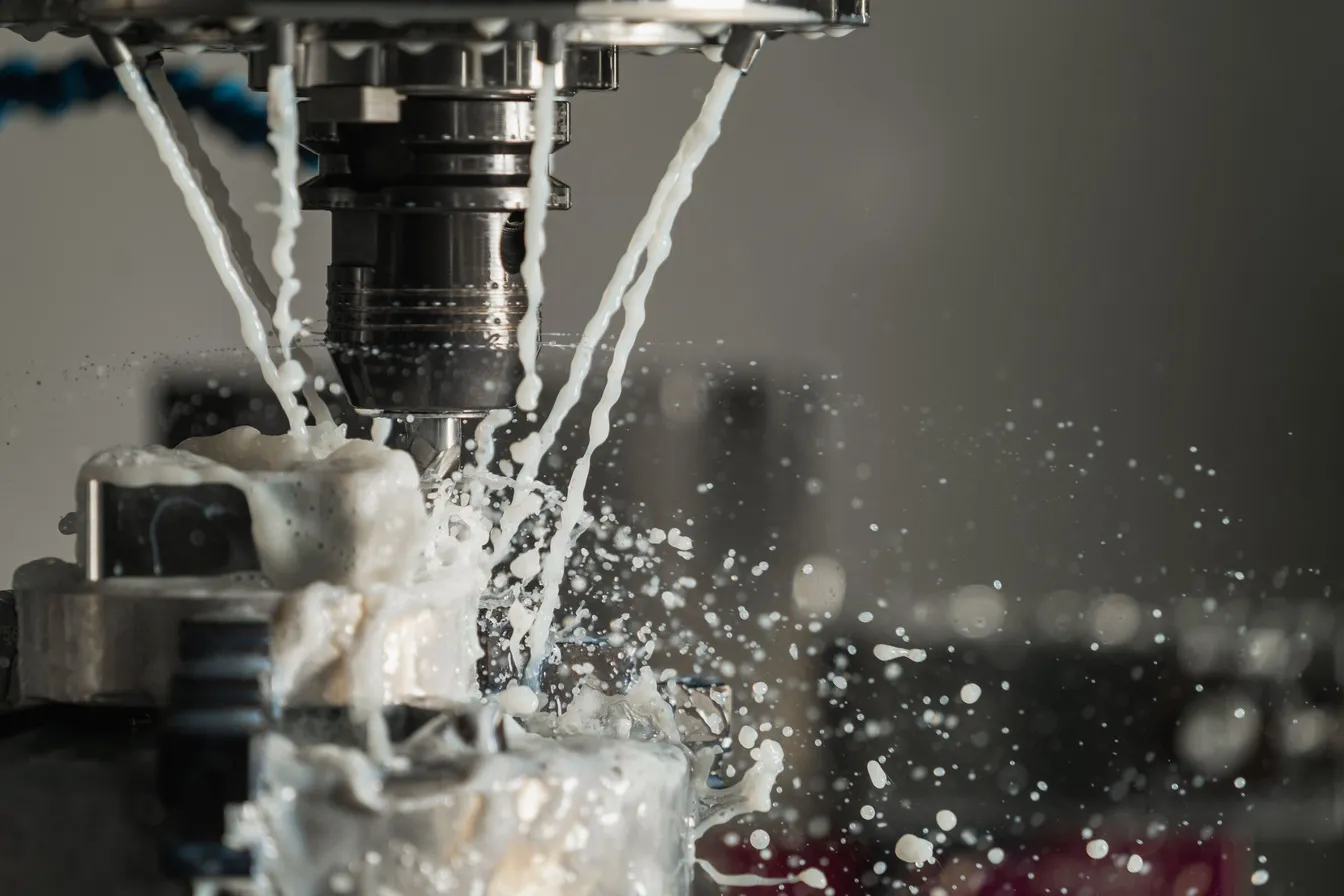
Cutting creates mechanical and thermal loads near the surface, and their effect depends on material, tooling, engagement, coolant delivery, stock condition, removal pattern, and the time between machining and inspection. Local temperature differences cause temporary dimensional change, while machining-induced residual stress persists after temperature equalizes.
A temperature-dependent measurement does not establish permanent deformation on its own. Record measurement temperature and timing wherever they could affect the acceptance decision.
Permanent deformation or damage
A clamp, press, deburring tool, handling event, or overload can yield or dent a weak section. Local evidence usually distinguishes damage from smooth global movement.
Elastic recovery, residual stress, movement, yielding, damage, and distortion are not interchangeable root causes, and treating them as one word is how investigations stall.
Why Fixture and Free-State Measurements Can Differ
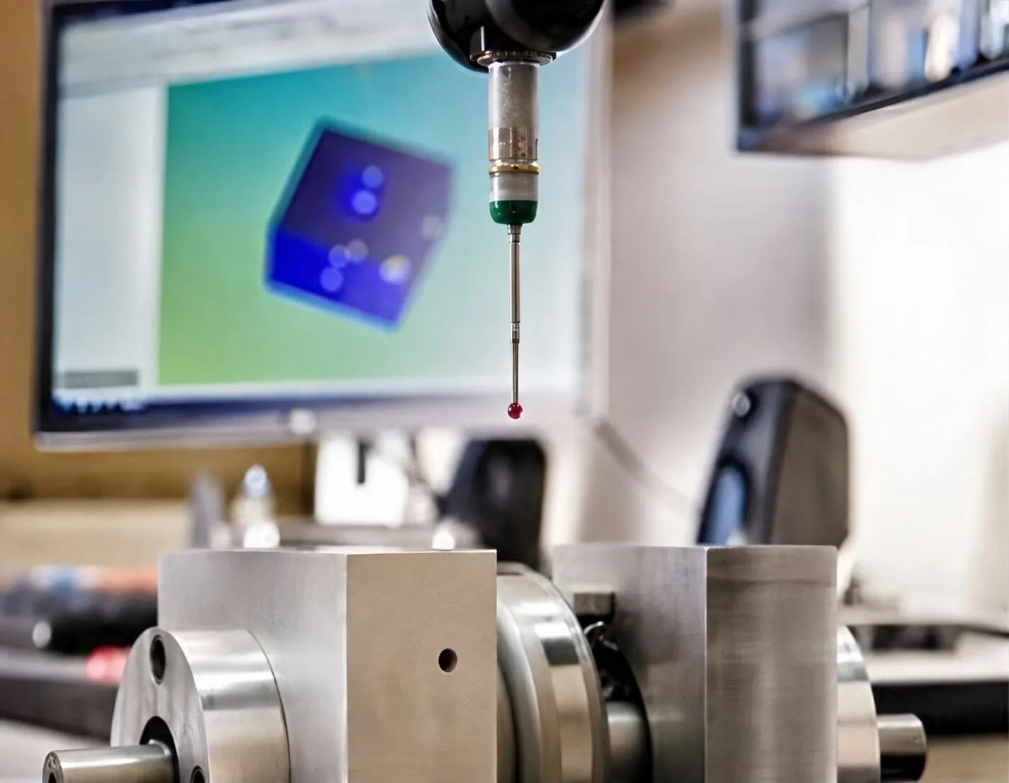
A fixture supplies the force that makes a restrained part look flat. In-process probing can validly control a machining operation without establishing final free-state conformity.
Inspection hardware need not reproduce assembly hardware, but it does have to establish the references and part condition the product definition requires. A free-state evaluation still needs physical support, and where support location or gravity orientation materially affects the result, the product definition or agreed inspection plan should define them. Support must not intentionally force the evaluated feature into conformity.
No state is universally correct. The design authority may need to define free-state, supported, authorized restrained, assembly-equivalent, or installed acceptance — including orientation, support, datums, timing, and finish state.
Requirements for flexible or non-rigid parts depend on the governing drawing system. ASME Y14.5-2018 (R2024) and ISO 10579:2010 provide different frameworks and should not be combined informally. The drawing should identify the applicable system, its edition, and any authorized restrained-state requirement, and standards get revised, so confirm current status when the drawing is released.
A supplier should not invent restraint to obtain a passing result, change the specified datum reference frame on its own, or substitute an in-process result for authorized final acceptance. Where the wider problem involves mating components or assembly evidence, see why inspected CNC parts can still fail assembly.
Geometry and Material Factors That Change the Risk
Risk rises when stiffness is low in the direction of cutting, clamping, gravity, or assembly loads. The geometry that matters is wall thickness, unsupported span, thin floors, open frames, deep pockets, ribs, and flanges.
Heavy or one-sided removal exposes an asymmetric stress field while reducing stiffness at the same time. Plate, bar, extrusion, forging, and casting stock each carry a different history, and alloy and temper do not describe that history fully.
A small free-state change may be functionally irrelevant where the product definition permits it — and unacceptable at a mounting plane, bearing relationship, seal, or locator. Tolerances should follow function, as covered in which CNC machining features need tight tolerances.
What Manufacturing Planning Can Do
Planning should address the suspected mechanism rather than run down a standard list of thin-wall tips.
- Support and clamps. Place support where it reacts cutting loads without displacing weak functional regions. More contact improves stability and can also restrict access or overconstrain the part.
- Roughing and finishing. Staged or better-balanced removal reduces abrupt changes in stiffness and stress balance. Symmetry helps some parts and eliminates no unknown residual stress.
- Temporary structure. Sacrificial material, tabs, temporary ribs, or bridges preserve stiffness during roughing. Plan their removal sequence and a final-state check, because releasing support can expose more movement.
- Intermediate release. Releasing or re-fixturing between stages reveals movement before final cutting, at the cost of setup variation, and it needs adequate datum recovery and stock.
- Tool system. Review reach, overhang, engagement, tool condition, and cutting stability when surface error suggests combined tool and workpiece flexibility.
- Inspection timing. Intermediate results show when movement begins. They do not replace the specified final acceptance condition.
- Later processes. Evaluate each applicable process separately. Anodizing and plating alter dimensions, surfaces, edges, threads, and masking transitions; heat treatment and welding change material properties, residual-stress distribution, or geometry. The drawing and inspection plan should identify the stage at which acceptance applies.
Five-axis access or a more rigid machine improves a setup without automatically resolving clamp recovery, residual stress, or an undefined acceptance condition. A DFM and engineering review should connect geometry, blank state, workholding, process sequence, inspection, and assembly.
Symptom-to-Investigation Table
| Observed symptom | Possible contributors | What to verify first |
|---|---|---|
| Local change near a clamp point | Fixture displacement, concentrated support, yielding or damage | Clamp location, support, free-state result, local evidence |
| Whole frame or housing twists after release | Residual-stress redistribution, global fixture recovery, asymmetric removal, low stiffness | Stock condition, restraint, roughing sequence, intermediate results |
| Error is greatest near the middle of an unsupported wall | Wall deflection, tool-system deflection, limited support, unstable engagement | Wall span, support, engagement, tool reach |
| Geometry changes during or after roughing | Residual-stress redistribution, reduced stiffness, process sequence | Blank condition, removal sequence, measurements between stages |
| Part passes while restrained but changes in the free state | Fixture-induced recovery, inspection-state mismatch | Acceptance state, authorized restraint, support, records |
The table gives investigation paths, not proven causes.
What Buyers Should Define in the Drawing and RFQ
Not every project needs every item below. They become relevant once distortion, measurement state, or assembly restraint could affect quotation or acceptance.
- Controlled 3D model, drawing, revision, and governing drawing standard
- Alloy, temper, required material condition, and relevant stock form
- Blank dimensions or near-net information needed to assess the amount and asymmetry of removal
- Final minimum wall thickness and unsupported height, length, or span
- Open frames, deep pockets, thin floors, ribs, flanges, and large one-sided removal areas
- Mounting, locating, sealing, bearing, and other functional interfaces
- Approved datum strategy and functionally important geometric relationships
- Free-state, supported, authorized restrained, assembly-equivalent, or installed acceptance condition
- Required orientation, supports, restraint, preload, or fastener sequence where necessary
- Inspection stage before or after finishing, heat treatment, welding, or another process
- Mating-part information, inspection-report scope, and prototype and production quantities
Stock dimensions, blank form, and the finished model let the reviewer evaluate removal amount and asymmetry. Do not try to substitute a universal removal-percentage limit for that review. For the broader quotation package, see what to include in a CNC machining drawing and RFQ.
Questions to Resolve During DFM Review
- Which mounting, locating, bearing, sealing, or assembly interfaces control function?
- Where are the weakest unsupported walls, floors, spans, and open sections?
- What are the stock form, blank dimensions, alloy, temper, and prior material condition?
- Is removal strongly asymmetric, and how does stiffness change by stage?
- Which roughing, release, re-fixturing, finishing, and post-processing sequence is proposed?
- Could the planned support or restraint displace a functional feature?
- In what state, orientation, and process stage must final acceptance occur?
- How will mating parts, preload, fastener sequence, or assembly restraint affect functional shape?
Align the Part State With the Functional Requirement
When a thin-walled part moves after unclamping, the visible movement is evidence rather than a verdict. A useful review connects the part’s geometry and material history with workholding, machining sequence, final inspection, finishing, and the shape the part has to hold in service.
Frequently Asked Questions
Can a thin-walled part pass inspection while clamped but fail in the free state?
Yes. A result obtained under restraint supports conformity only to the applicable requirement and authorized inspection condition. If the product definition requires free-state acceptance, the part has to be evaluated in that state, using support that does not intentionally force the controlled geometry into conformity.
Does stress-relieved material prevent post-machining distortion?
No. It may reduce certain initial residual stresses, but geometry, stiffness, machining-induced stress, workholding, sequence, and later processing can all still move the part.
Should a flexible CNC part be inspected while restrained?
Only when an approved restraint represents the acceptance requirement. The support, orientation, datum setup, and restraint have to be defined well enough to reproduce the decision.
Does a tighter tolerance solve thin-wall distortion?
No. A tighter tolerance changes the acceptance limit. It does not increase stiffness, change residual stress, correct workholding, or define the measurement state.
References
- Andreas Andersson Lassila et al., “Numerical Evaluation of Cutting Strategies for Thin-Walled Parts,” Scientific Reports, 2024
- Jakub Czyżycki, Paweł Twardowski, Natalia Znojkiewicz, “Analysis of the Displacement of Thin-Walled Workpiece Using a High-Speed Camera during Peripheral Milling of Aluminum Alloys,” Materials, 2021
- Jun Wang et al., “FEM-Based Simulation for Workpiece Deformation in Thin-Wall Milling,” International Journal of Automation Technology, 2015
- Daniel Weber et al., “Analysis of Machining-Induced Residual Stresses of Milled Aluminum Workpieces, Their Repeatability, and Their Resulting Distortion,” The International Journal of Advanced Manufacturing Technology, 2021
- M. Landwehr et al., “The Finite Cell Method for the Prediction of Machining Distortion Caused by Initial Residual Stresses in Milling,” Procedia CIRP, 2021
- ASME Y14.5-2018 (R2024), Dimensioning and Tolerancing
- ISO 10579:2010, Dimensioning and Tolerancing — Non-Rigid Parts